

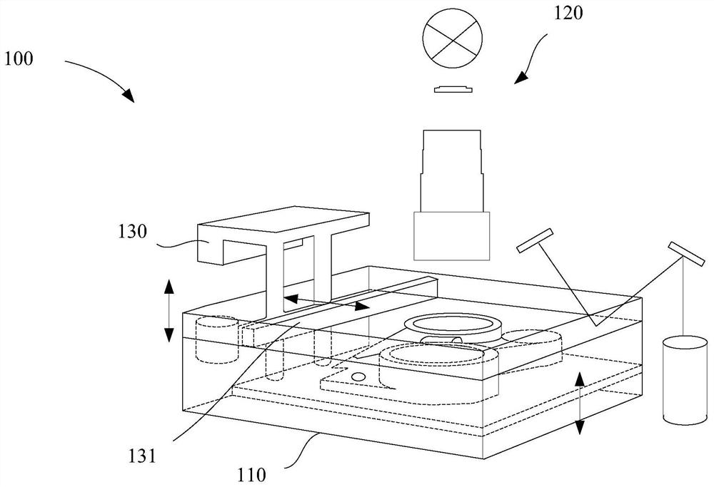
Light-curing three-dimensional printing method and device
A 3D printing and photocuring technology, applied in the field of image exposure systems, can solve problems such as deformation of photocurable resins, and achieve the effect of reducing shrinkage accumulation
- Summary
- Abstract
- Description
- Claims
- Application Information
AI Technical Summary
Problems solved by technology
Method used
Image

Examples
no. 1 example
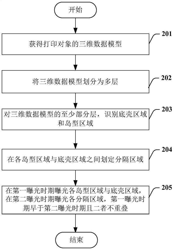
[0043] figure 2 A flow chart of the photocuring three-dimensional printing method according to the first embodiment of the present invention is shown. refer to figure 2 As shown, the method includes the following steps:
[0044] In step 201, obtain the three-dimensional model data of the printing object;
[0045] In step 202, the three-dimensional data model is divided into multiple layers;
[0046] In step 203, for at least some layers of the three-dimensional data model, identifying the bottom shell region whose size reaches a threshold value and the island type area of one or more supports for supporting the bottom shell region in the layer;
[0047] In step 204, a separation area is defined between each island type area and the bottom shell area;
[0048] In step 205, when exposing each island-shaped area and the bottom shell area, the area other than each partition area is exposed during the first exposure period, and each partition area is exposed during the seco...
no. 2 example
[0060] Figure 5 A flowchart of a photocuring three-dimensional printing method according to an embodiment of the present invention is shown. refer to Figure 5 As shown, the method includes the following steps:
[0061] In step 501, obtain the three-dimensional model data of the printing object;
[0062] In step 502, the three-dimensional data model is divided into multiple layers;
[0063] In step 503, for at least a partial layer of the three-dimensional data model, identifying a bottom shell region whose size reaches a threshold value and an island-shaped region where one or more supports for supporting the bottom shell region are in the layer;
[0064] In step 504, a separation area is defined between each island type area and the bottom shell area;
[0065] In step 505, when exposing each island-shaped area and the bottom shell area, the area other than each partition area is exposed in one exposure period, and each partition area is exposed in a second exposure peri...
no. 3 example
[0077] Figure 6 A flow chart of a photocuring three-dimensional printing method according to a third embodiment of the present invention is shown. refer to Figure 6 As shown, the method includes the following steps:
[0078] In step 601, obtain the three-dimensional model data of the printing object;
[0079] In step 602, the three-dimensional data model is divided into multiple layers;
[0080] In step 603, for at least some layers of the three-dimensional data model, identifying a bottom shell region whose size reaches a threshold value and an island-shaped region where one or more supports for supporting the bottom shell region are in the layer;
[0081] In step 604, a separation area is defined between each island type area and the bottom shell area;
[0082] At step 605, dividing the bottom shell region into complementary first and second patterns;
[0083] In step 606, the first pattern of the bottom shell area and the island-shaped areas are exposed through the f...
PUM
 Abstract
Description
Claims
Application Information