AI technical title is built by PatSnap AI team. It summarizes the technical point description of the patent document.
A pipe bending machine and pipe bending technology, which is applied in the directions of forming tools, manufacturing tools, heat exchange equipment, etc., can solve problems such as difficulty in demoulding the bending mold
Pending Publication Date: 2018-04-13
SUZHOU XINYUAN ELECTRICAL APPLIANCE
View PDF10 Cites 0 Cited by
Summary
Abstract
Description
Claims
Application Information
AI Technical Summary
This helps you quickly interpret patents by identifying the three key elements:
Problems solved by technology
Method used
Benefits of technology
Problems solved by technology
[0003] In order to solve the above-mentioned problem of difficult demoulding of the pipe bending die, the present invention provides a pipe bending die for a pipe bending machine
Method used
Image
Click on the blue label to locate the original text in one second.
Reading with bidirectional positioning of images and text.
Examples
Embodiment 1
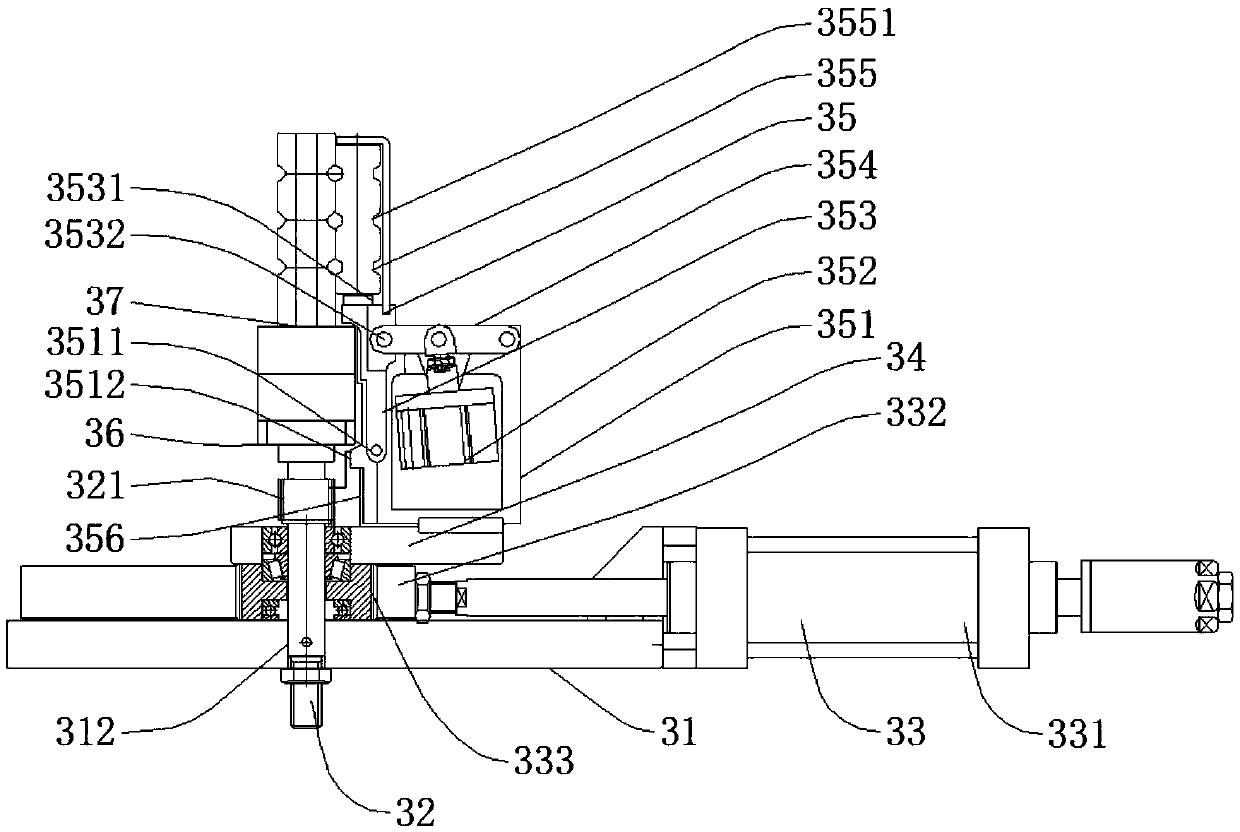
[0025] Please see attached Figure 1-6 , a pipe bending die for a pipe bending machine, comprising a fixed base plate 31, a fixed shaft 32, a drive mechanism 33, a movable pulley fixed plate 34, a movable pulley mechanism 35, a fixed pulley fixed plate 36, and a fixed pulley mechanism 37;
[0026] The middle part of the fixed bottom plate 31 is provided with a fixed hole 31;
[0027] The fixed shaft 32 is a stepped gear shaft;
[0028] The upper part of the fixed shaft 32 is provided with gear teeth 321, and the fixed shaft 32 is matched with the fixed hole 31;
[0029] A fixed key or a fixed pin is also provided between the fixed shaft 32 and the fixed hole 31;
[0030] The driving mechanism 33 includes a driving hydraulic cylinder 331, a driving rack 332, and a driving gear 333;
[0031] The driving hydraulic cylinder 331 is fixed on the fixed base plate 31;
[0032] The drive gear 333 is installed on the fixed shaft 32 and is arranged next to the fixed base plate 31; th...
[0081] The fixed pulley 371 includes a first half fixed pulley 3711 and a second half fixed pulley 3712;
[0082] The first semi-fixed pulley 3711 and the second semi-fixed pulley 3712 are incomplete pulleys; the outer side is an arc surface, and the inner side is a plane;
[0083] The circular arc surfaces of the first semi-fixed pulley 3711 and the second semi-fixed pulley 3712 are stepped; they include the upper bending part 370 and the lower fixing part 3700;
[0084] The fixed part 3700 is provided with a fixed boss 3713, and the bent pipe working part 370 is provided with an annular first base pipe groove 3714 with equal spacing;
[0085] An elbow fixing part fixing hole 3701 is provided on the upper side of the fixing part 3700;
[0086] The bottom of the bent pipe working part 370 is provided wit...
PUM
Abstract
The invention discloses a pipe bending die of a pipe bending machine. The pipe bending die of the pipe bending machine comprises a fixing bottom plate, a fixing shaft, a drive mechanism, a movable pulley fixing plate, a movable pulley mechanism, a fixed pulley fixing plate and a fixed pulley mechanism. The fixing shaft is arranged on the middle portion of the fixing bottom plate and provided withgear teeth. The drive mechanism comprises a drive hydraulic cylinder, a drive rack and a drive gear. The drive hydraulic cylinder is fixed to the fixing bottom plate. The drive gear is arranged on thefixing shaft. The drive rack is fixed to a piston rod of the drive hydraulic cylinder and engaged with the drive gear. The movable pulley fixing plate is fixed to the drive gear. The fixed pulley fixing plate is in a strip shape, and one end of the fixed pulley fixing plate is arranged on the fixing shaft, located on the upper portion of the movable pulley fixing plate and the upper portions of gear teeth and hinged to the fixing shaft. The fixed pulley mechanism is arranged on the fixed pulley fixing plate. The movable pulley mechanism is fixed to the movable pulley fixing plate. When the pipe bending die of the pipe bending machine is used, bending for different radii can be achieved by replacing a pipe bending working part, and meanwhile, the distance between the movable pulley mechanism fixing frame and the pipe bending working part needs to be adjusted.
Description
technical field [0001] The invention belongs to the technical field of pipe bending machines, and in particular relates to a pipe bending die of a pipe bending machine. Background technique [0002] The pipe bending mold is a mold used to bend straight pipes into various shapes of pipes. When in use, it is installed on the pipe bending machine, and the straight pipes are bent and formed by machine or manpower. The pipe bending mold generally includes the wheel mold body, the main mold and the guide mold. This kind of pipe bending mold will be wound after the pipe bending is completed. The conventional solution is to set a gap on the pipe bending mold. After the pipe is bent on the pipe bending mold and the pipe bending mold is rotated, the demoulding can be realized. However, the bending angle of this pipe bending mold is still limited. limited. There is also a pipe bending mold that divides the mold into upper and lower parts from the middle. This kind of mold solves the ...
Claims
Application Information
Patent Timeline
Application Date:The date an application was filed.
Publication Date:The date a patent or application was officially published.
First Publication Date:The earliest publication date of a patent with the same application number.
Issue Date:Publication date of the patent grant document.
PCT Entry Date:The Entry date of PCT National Phase.
Estimated Expiry Date:The statutory expiry date of a patent right according to the Patent Law, and it is the longest term of protection that the patent right can achieve without the termination of the patent right due to other reasons(Term extension factor has been taken into account ).
Invalid Date:Actual expiry date is based on effective date or publication date of legal transaction data of invalid patent.

