control device

一种控制装置、方式控制的技术,应用在电气控制、发动机控制、装料系统等方向,能够解决燃烧失败、管路火花塞覆液点火失败等问题,达到抑制结露的效果

Active Publication Date: 2020-04-24
HITACHI ASTEMO LTD
View PDF5 Cites 0 Cited by
  • Summary
  • Abstract
  • Description
  • Claims
  • Application Information

AI Technical Summary

Problems solved by technology

As a result, ignition failure may occur due to corrosion and deterioration of piping, etc., spark plug flooding caused by inflow into the combustion chamber, etc., and further, fire extinguishing phenomenon of combustion failure may occur.

Method used


Image

  • control device
  • control device
  • control device

Examples


Embodiment Construction

[0028]

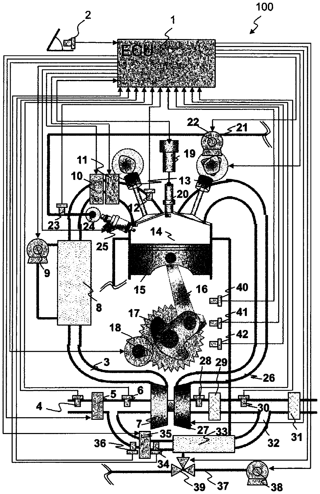
[0029] Next, an engine control device as an embodiment of the present invention will be described. The premise is that the engine is an automotive engine equipped with an exhaust gas recirculation mechanism that recirculates exhaust gas from the exhaust pipe to the intake pipe, and a compressor on the intake pipe.

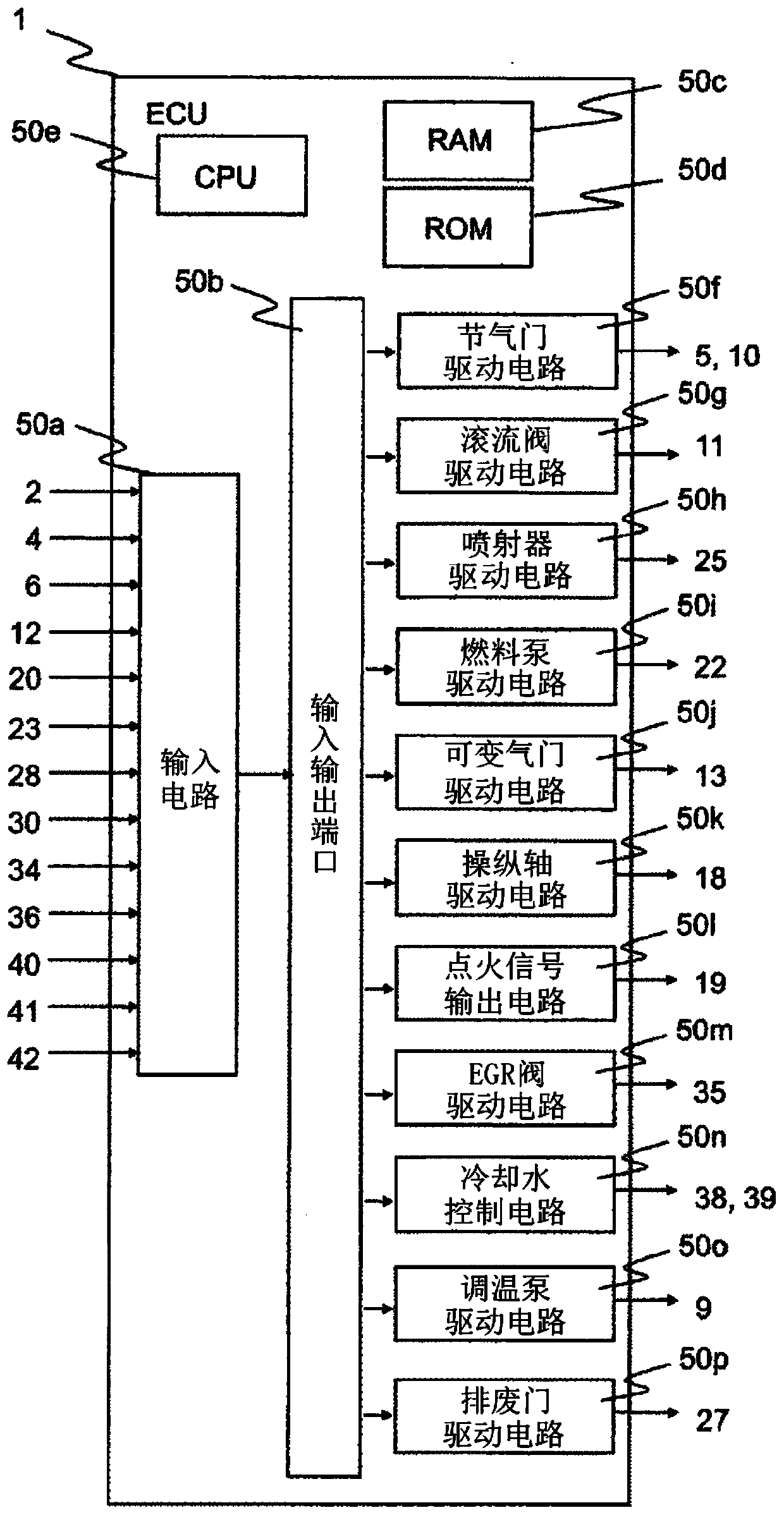
[0030] figure 1 It is a system configuration diagram of the automotive engine system of the present embodiment. An ECU (Electronic Control Unit) 1 is a control device in this embodiment. The accelerator opening sensor 2 is a sensor that detects the opening of an accelerator equipped in the vehicle. The engine 100 is an automotive engine that implements spark ignition combustion or compression self-ignition combustion.

[0031] The engine 100 includes an intake pipe 3 and an exhaust pipe 26 . The intake pipe 3 includes an air flow sensor 4 for measuring the amount of intake air, an adjustment valve 5 for adjusting the flow area of ​​the intake pipe 3 ...


PUM


Abstract

The present invention provides an engine control device capable of suppressing dew condensation in an exhaust gas recirculation pipe and the like. The control device of the present invention controls an engine equipped with an exhaust gas recirculation mechanism for recirculating exhaust gas from an exhaust pipe to an intake pipe, and a compressor on the intake pipe. The control device controls the exhaust gas recirculation mechanism according to the pressure and humidity in the intake pipe.

Description

technical field [0001] The present invention relates to a control device mounted on an automobile or the like. Background technique [0002] Today's automobiles require high efficiency and clean exhaust gas from the standpoint of environmental protection and energy saving. As a means of improving efficiency, improvements in engine structure through downsizing, reduction in the number of cylinders, and increase in compression ratio can be cited. Downsizing increases the temperature of the air-fuel mixture in the combustion chamber, making abnormal combustion prone to occur. Therefore, exhaust gas recirculation (hereinafter referred to as EGR: Exhaust Gas Recirculation) is introduced to reduce the temperature of the air-fuel mixture in the combustion chamber to suppress abnormal combustion. [0003] In the EGR system, the components of the circulating gas contain water vapor, and dew condensation may occur when the water vapor is mixed with the fresh air and combined with the...

Claims


Application Information

Patent Timeline
Patent Type & Authority Patents(China)
IPC IPC(8): F02M26/03F02D21/08F02D23/00
CPCF02D21/08F02D23/00F02D41/0077F02D2200/0406F02D2200/0418F02M26/06F02M26/21Y02T10/40F02M26/03F02M26/25F02M26/30F02D2200/0414
Inventor 绪方健一郎有原仪信猿渡匡行
Owner HITACHI ASTEMO LTD
Why Eureka
Try Eureka