Plate overturning machine and numerical-control cutting production line thereof

A technology of turning machines and plates, applied in the directions of conveyors, conveyor objects, transportation and packaging, etc., can solve the problems of low operation efficiency of plate workpieces, high labor intensity of workers, affecting processing quality, etc., and achieve simple and reasonable structure and labor costs. Reduced, practical effect

Pending Publication Date: 2018-04-24
FOSHAN HAOYANG WOODWORK MACHINERY MFR
View PDF1 Cites 15 Cited by
  • Summary
  • Abstract
  • Description
  • Claims
  • Application Information

AI Technical Summary

Problems solved by technology

[0002] Existing CNC cutting machines generally can only process one side of the plate workpiece. If the plate workpiece needs to be processed on both sides, it is necessary to arrange workers to flip the plate workpiece. When the plate workpiece is large in size or heavy in weight, The operation of the workers is very troublesome and requires a lot of physical strength. In the long run, the labor intensity of the workers is very high, and the operation efficiency of manually turning over the plate workpiece is low. It is difficult to locate the position after each turning, which affects its processing quality; For this reason, in response to this problem, different turning devices have gradually appeared on the market, such as: Chinese patent document CN106743423A disclosed a composite plate turning machine on May 31, 2017, and specifically disclosed: including: an upper frame, a lower frame , chain, connecting rod, plate clamping frame, pulley platform, motor, infrared sensor, PLC control system; the shell is a net column structure, and the water outlet is set at the bottom of the shell; the lower frame is directly set on any part of the production line Below the roller conveying mechanism, the direction is parallel to the axial direction of the roller. The middle of the lower frame is a hollow structure. The midpoint of the hollow position in the horizontal direction is provided with a power sprocket, and the left and right sides of the power sprocket in the horizontal direction are respectively provided with a lower frame sprocket. 1 and the lower frame sprocket 2, the lower frame sprocket 3 and the lower frame sprocket 4 are respectively set under the left and right sides of the power sprocket; the upper frame is an inverted U-shaped hollow frame, and the upper frame is set in contact with the lower frame The upper part of the lower frame is stored, the horizontal direction of the upper frame is parallel to the lower frame, and the vertical direction is perpendicular to the axial direction of the roller. The inner diameter of the upper frame is larger than the width of the roller frame. Two upper frame sprockets, the upper frame sprockets opposite the two inner walls are hollow without connection; the motor is connected to the power sprocket, and the motor provides power for the chain movement; the spindle tension is set on the upper frame chain Wheel and power sprocket, lower frame sprocket 1, lower frame sprocket 2, the chain is sandwiched by lower frame sprocket 3, lower frame sprocket net and power sprocket; one end of the connecting rod is located on the upper frame One side of the chain is connected to a sleeve shaft and is clamped by the limit piece. The connecting rod can rotate around the cylindrical surface of the sleeve; The shaft rotates; the structure of the plate clamping frame is a plurality of small rectangular frame bodies with a width smaller than the gap between the idlers and the same size. A vertical longitudinal connecting rod b is respectively arranged in the middle of the left and right sides of the same size. A large rectangular frame body connected in series with small rectangular frame bodies, one side of the small rectangular frame body a in the middle is provided with a circular arc transition surface, and the other side is provided with a connecting shaft; the plate clamping frame is placed between the production line and the idler roller In the gap between two supporting rollers whose axes are parallel to each other, the small rectangular frame body a in the middle of the plate clamping frame is supported on the pulley platform; the pulley platform is placed on the top surface of the lower frame, under the bottom surface of the small rectangular frame body a, the pulley There are several pulleys on the top surface of the platform, and the height of the pulley platform is adjustable. By adjusting the height of the pulley platform, the height of the bottom surface of the plate clamping frame is slightly lower than the top surface of the roller on the roller conveyor table; the infrared sensor is set on the top of the upper frame Inside; the PLC control system is set in the hollow position of the lower frame to control the whole units running
The flipping machine uses the technical solution of in-situ flipping to flip the plate, and the flipped plate is directly returned to the CNC cutting machine for further processing. The structure is complex and the manufacturing cost is high, and it can only be applied to a single CNC cutting machine.

Method used


Image

  • Plate overturning machine and numerical-control cutting production line thereof
  • Plate overturning machine and numerical-control cutting production line thereof
  • Plate overturning machine and numerical-control cutting production line thereof

Examples


no. 1 example

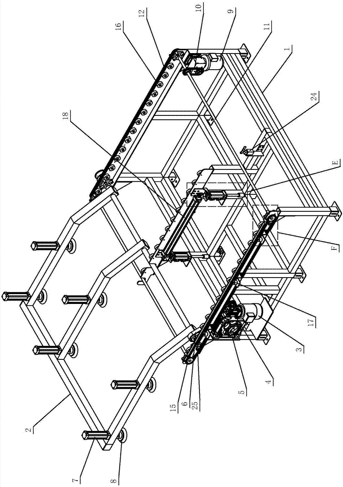
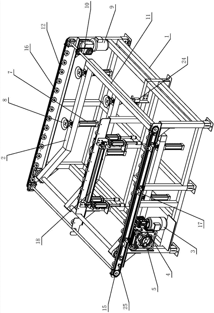
[0027] see Figure 1-Figure 6, the CNC cutting production line involved in this embodiment includes a plate turning machine A, a numerical control cutting machine B and an electric control cabinet D, the plate turning machine A is set on the side of the numerical control cutting machine B, and the electronic control The cabinet D is located on the other side of the CNC cutting machine B, and the plate turning machine A transports the turned plate-shaped workpiece C to the CNC cutting machine B; the CNC cutting machine B and the plate turning machine A are respectively controlled by the electric control cabinet D. Wherein, the plate turning machine includes an equipment frame 1 for carrying various mechanisms, and the equipment frame 1 is provided with a turning mechanism and a conveying mechanism; the turning mechanism includes a turning arm 2, a sucker assembly and a turning drive assembly; the turning arm 2 rotates on one side Connect the equipment frame 1; the suction cup a...

no. 2 example

[0050] see Figure 17-Figure 19 , this plate turning machine and its CNC cutting production line are different from the first embodiment in that the CNC cutting production line involved includes a plate turning machine A, two CNC cutting machines B and an electric control cabinet D. The plate turning machine A is set between two CNC cutting machines B, the electric control cabinet D is located on the side of any CNC cutting machine B, and the plate turning machine A picks up the plate-shaped workpiece from one CNC cutting machine B C turns over and conveys it to another CNC cutting machine B to realize the connection between two CNC cutting machines B to meet different production needs; CNC cutting machine B and plate turning machine A are respectively powered Control cabinet D control.

[0051] Furthermore, in order to cooperate with the connection of two CNC cutting machines B, the moving starting position of the block 13 is set on the other side of the feeding area; the push...


PUM


Abstract

A plate turning machine, comprising an equipment frame, on which a turning mechanism and a conveying mechanism are arranged; the turning mechanism includes a turning arm, a suction cup assembly and a turning drive assembly; More than one group and respectively assembled on the turning arm; the turning drive assembly is set on the equipment rack and drives the turning arm to turn back and forth between the corresponding CNC cutting machine and the equipment rack where it is located, so as to turn the plate on the CNC cutting machine The workpiece is turned over and placed in the feeding area of ​​the equipment rack; the conveying mechanism is located in the feeding area of ​​the equipment rack, which includes a conveying chain with a stopper and a conveying drive assembly. The conveying drive assembly is arranged on the equipment rack and drives the conveying When the chain runs, the block moves with the conveyor chain and drives the plate-shaped workpiece in the feeding area to be transported to the corresponding CNC cutting machine. The invention has the characteristics of reliable and stable performance, high turnover efficiency, low labor intensity, and multi-machine combination can be realized.

Description

technical field [0001] The invention relates to a sheet material processing production equipment and system, in particular to a sheet material turning machine and a numerical control cutting production line thereof. Background technique [0002] Existing CNC cutting machines generally can only process one side of the plate workpiece. If the plate workpiece needs to be processed on both sides, it is necessary to arrange workers to flip the plate workpiece. When the plate workpiece is large in size or heavy in weight, The operation of the workers is very troublesome and requires a lot of physical strength. In the long run, the labor intensity of the workers is very high, and the operation efficiency of manually turning over the plate workpiece is low. It is difficult to locate the position after each turning, which affects its processing quality; For this reason, in response to this problem, different turning devices have gradually appeared on the market, such as: Chinese pate...

Claims


Application Information

Patent Timeline
Patent Type & Authority Applications(China)
IPC IPC(8): B65G47/248B65G47/91
CPCB65G47/248B65G47/915B65G2201/022
Inventor 萧浩强
Owner FOSHAN HAOYANG WOODWORK MACHINERY MFR
Why Eureka
Try Eureka