Novel LED lamp device

An LED light device and a new type of technology can be used in lighting devices, fixed lighting devices, components of lighting devices, etc., and can solve problems such as death, safety hazards, and falling lights.

Inactive Publication Date: 2018-05-08
张莉笛
View PDF0 Cites 0 Cited by
  • Summary
  • Abstract
  • Description
  • Claims
  • Application Information

AI Technical Summary

Problems solved by technology

[0002] In modern home life, plug-in LED lights are often installed near the bedside of the bedroom for night lighting. The traditional plug-in LED light setting mode is too simple, and the plug-in between the lamp head and the lamp holder is only achieved by friction. state, but this locking method is extremely unstable, often due to human accidental touch or self-weight and other reasons, causing loose plugging or falling lights, which has great disadvantages. At the same time, because the lamp holder of the LED lamp is generally They are all set near the head of the bed and are directly charged. For some people who lack safety awareness (such as young children), when a metal rod is inserted into the lamp holder and contacts the conductive part, it will cause electric shock accidents. , will cause death in severe cases, and there is a greater potential safety hazard

Method used


Image

  • Novel LED lamp device
  • Novel LED lamp device
  • Novel LED lamp device

Examples


Embodiment Construction

[0023] All features disclosed in this specification, or steps in all methods or processes disclosed, may be combined in any manner, except for mutually exclusive features and / or steps.

[0024] Any feature disclosed in this specification (including any appended claims, abstract and drawings), unless expressly stated otherwise, may be replaced by alternative features which are equivalent or serve a similar purpose. That is, unless expressly stated otherwise, each feature is one example only of a series of equivalent or similar features.

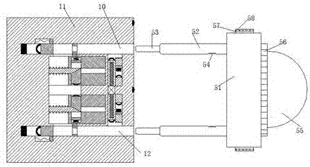
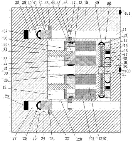
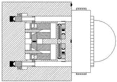
[0025] Such as Figure 1 to Figure 4As shown, a new type of LED lamp device of the device of the present invention includes a lamp holder 10 fixedly installed in the wall and a lamp head 51 matched with the lamp holder 10, and the upper and lower sides of the lamp holder 10 are symmetrical An inserting groove 11 with the port facing right is provided, a sliding cavity 12 is provided between the two inserting grooves 11, and a connecting first...


PUM


Abstract

The invention discloses a novel LED lamp device. The novel LED lamp device comprises a lamp holder part fixedly mounted on a wall, and a bulb holder part matched with the lamp holder part, wherein insertion grooves of which openings are rightward are formed in the lamp holder part in up-down symmetry; sliding cavities are formed between the two insertion grooves; a first communication groove is formed in the left side of the position between the two sliding cavities; second communication grooves are formed between the sliding cavities and the insertion grooves; sliding blocks capable of sliding left and right are mounted in the sliding cavities; pushing grooves of which openings face the first communication groove are formed in the sliding blocks; third communication grooves which are through left and right and penetrate through the pushing grooves are formed in the sliding blocks; pushing blocks capable of sliding up and down are mounted in the pushing grooves; fourth communication grooves which are through left and right are formed in the pushing blocks; first diagonal planes are arranged on the end walls, close to the first communication groove, of the fourth communication grooves; fixed connecting arms are fixedly mounted on the left end walls of the sliding cavities; and the right ends of the fixed connecting arms stretch into the third communication grooves and are provided with second diagonal planes matched with the first diagonal planes.

Description

technical field [0001] The invention relates to the field of LED lamps, in particular to a novel LED lamp device. Background technique [0002] In modern home life, plug-in LED lights are often installed near the bedside of the bedroom for night lighting. The traditional plug-in LED light setting mode is too simple, and the plug-in between the lamp head and the lamp holder is only achieved by friction. state, but this locking method is extremely unstable, often due to human accidental touch or self-weight, etc., causing loose plugging or falling lights, which has great disadvantages. At the same time, because the lamp holder of the LED lamp is generally They are all set near the head of the bed and are directly charged. For some people who lack safety awareness (such as young children), when a metal rod is inserted into the lamp holder and contacts the conductive part, it will cause an electric shock accident. , will cause death in severe cases, and there is a greater pot...

Claims


Application Information

Patent Timeline
Patent Type & Authority Applications(China)
IPC IPC(8): F21S8/00F21V17/10F21V17/12F21V19/00F21V23/06F21V25/00F21Y115/10F21W131/301
CPCF21S8/00F21V17/104F21V17/12F21V19/001F21V23/06F21V25/00F21W2131/301F21Y2115/10
Inventor 张莉笛
Owner 张莉笛
Why Eureka
Try Eureka