Laser welding method for narrow space of casing

A laser welding, narrow space technology, used in laser welding equipment, welding equipment, metal processing equipment, etc., to improve welding quality and stability, realize welding automation, and improve the effect of melting width

Active Publication Date: 2018-05-11
SHENYANG LIMING AERO-ENGINE GROUP CORPORATION
View PDF5 Cites 6 Cited by
  • Summary
  • Abstract
  • Description
  • Claims
  • Application Information

AI Technical Summary

Problems solved by technology

[0003] The purpose of the present invention is to overcome the shortcomings of the above-mentioned prior art, and provide a laser welding method in a narrow space of the casing, so that the welding heat input and the quality of the weld seam can b...

Method used


Image

  • Laser welding method for narrow space of casing
  • Laser welding method for narrow space of casing
  • Laser welding method for narrow space of casing

Examples


Embodiment 1

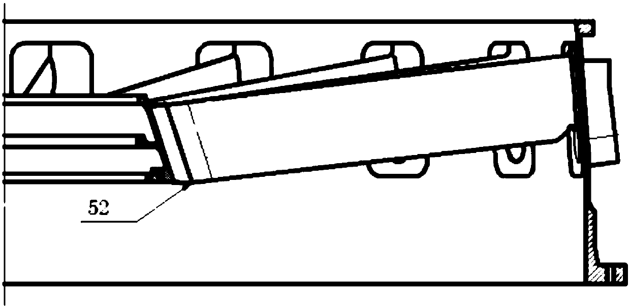
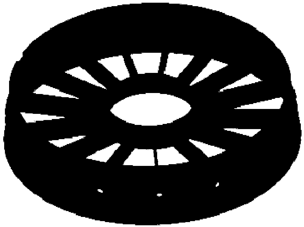
[0031] A laser welding method for the narrow space of the casing, the schematic diagram of the three-dimensional model of the casing is shown in figure 2 shown, including the following steps:

[0032] Step 1, preparation before welding:

[0033] Before welding, use acetone to remove oil stains on the joint section of the parts and the 8-12 mm area on both sides of the joint;

[0034] Step 2, assembly tack welding:

[0035] Assemble the fixed support plate, the outer casing and the front section of the inner ring on the welding tool, and use argon arc welding to position the front section of the inner ring and the fixed support plate to ensure that the matching gap is ≤0.1mm;

[0036] Step 3, laser welding:

[0037] (1) Robotic fiber laser welding equipment with galvanometer-type laser swing welding head is adopted. The focal length of the laser head is above 300mm to ensure the accessibility of the laser, so that the end of the welding seam reaches the bottom of the surfac...

Embodiment 2

[0042] A laser welding method for the narrow space of the casing, the schematic diagram of the three-dimensional model of the casing is shown in figure 2 shown, including the following steps:

[0043] Step 1, preparation before welding:

[0044] Before welding, use acetone to remove oil stains on the joint section of the parts and the 8-12 mm area on both sides of the joint;

[0045] Step 2, assembly tack welding:

[0046] Assemble the fixed support plate, the outer casing and the front section of the inner ring on the welding tool, and use argon arc welding to position the front section of the inner ring and the fixed support plate to ensure that the matching gap is ≤0.1mm;

[0047] Step 3, laser welding:

[0048] (1) Robotic fiber laser welding equipment with galvanometer-type laser swing welding head is adopted. The focal length of the laser head is above 300mm to ensure the accessibility of the laser, so that the end of the welding seam reaches the bottom of the surfac...

Embodiment 3

[0053] A laser welding method for the narrow space of the casing, the schematic diagram of the three-dimensional model of the casing is shown in figure 2 shown, including the following steps:

[0054] Step 1, preparation before welding:

[0055] Before welding, use acetone to remove oil stains on the joint section of the parts and the 8-12 mm area on both sides of the joint;

[0056] Step 2, assembly tack welding:

[0057] Assemble the fixed support plate, the outer casing and the front section of the inner ring on the welding tool, and use argon arc welding to position the front section of the inner ring and the fixed support plate to ensure that the matching gap is ≤0.1mm;

[0058] Step 3, laser welding:

[0059] (1) Robotic fiber laser welding equipment with galvanometer-type laser swing welding head is adopted. The focal length of the laser head is above 300mm to ensure the accessibility of the laser, so that the end of the welding seam reaches the bottom of the surfac...


PUM

PropertyMeasurementUnit
Thicknessaaaaaaaaaa
Defocus amountaaaaaaaaaa

Abstract

The invention discloses a laser welding method for narrow space of a casing. The laser welding method comprises the following steps that oil removal treatment is carried out on a section of a joint ofa part and two sides of the joint before welding; a support plate, an outer casing and an inner ring front section are assembled, the inner ring front section and the fixing support plate are positioned, and the matching clearance is ensured to be less than or equal to 0.1mm; a robot optical fiber laser welding device is adopted, and inert gas protection is carried out on the front sides of weldjoints; corresponding welding parameters are controlled, and laser welding is carried out; and after welding is completed, the weld joints of the support plate and the inner ring front section are checked, the appearance of the weld joints is ensured to be in smooth transition with base material, the surfaces of the weld joints are free of cracks, burnthrough, overlaps and welding spatters, an x-ray bar anode coloring inspection is carried out, and no welding defect is found. By the adoption of the laser welding method, the welding heat input quantity and the weld joint forming quality are effectively controlled, welding deformation is reduced, the welding quality and the stability are greatly improved, finally, the problems of welding deformation of the gas inlet casing and testing and repairing cracks are solved.

Description

Technical field: [0001] The invention belongs to the technical field of aero-engine manufacturing, and in particular relates to a laser welding method in a narrow space of a casing. Background technique: [0002] An existing casing inner ring and fixed support plate, gas collecting hood and outer shell are welded by argon arc welding process, the deformation after welding is serious, and cracks occur frequently. The failure rate reached 88%, and the straightness of the fixed support plate exceeded 1mm; the gas collection hood and the outer ring shell, the inner ring and the fixed support plate were cracked and overhauled. And adding the rod anode inspection method, it was found that the argon arc weld of the inner ring and the fixed support plate has the problem of incomplete penetration, which is also the main reason for the high crack failure rate. The current argon arc welding process is limited by the arc stiffness and penetration depth , unable to fundamentally solve t...

Claims


Application Information

Patent Timeline
IPC IPC(8): B23K26/24B23K26/60
CPCB23K26/24B23K26/60
Inventor 杨烁曲伸宋文清李英葛沁
Owner SHENYANG LIMING AERO-ENGINE GROUP CORPORATION
Why Eureka
Try Eureka