Energy-saving lamp device

A technology of energy-saving lamps and lamp sockets, which is applied in lighting devices, fixed lighting devices, lighting auxiliary devices, etc., can solve the problems of unstable locking method, hidden dangers, loose plugging, etc., to achieve stable power supply, reduce hidden dangers, Avoid the effect of loose plugging

Inactive Publication Date: 2018-05-15
俞岳田
View PDF0 Cites 0 Cited by
  • Summary
  • Abstract
  • Description
  • Claims
  • Application Information

AI Technical Summary

Problems solved by technology

[0002] In modern home life, plug-in energy-saving lamps are often installed near the bedside of the bedroom for night lighting. The traditional plug-in energy-saving lamp setting mode is too simple, and the plug-in between the lamp head and the lamp holder is only achieved by friction. state, but this locking method is extremely unstable, often due to accidental human touch or self-weight, etc., causing loose plugs or falling lights, which has great disadvantages. At the same time, because the lamp holder of the energy-saving lamp is generally They are all set near the head of the bed and are directly charged. For some people who lack safety awareness (such as young children), when a metal rod is inserted into the lamp holder and contacts the conductive part, it will cause an electric shock accident. , will cause death in severe cases, and there is a greater potential safety hazard

Method used


Image

  • Energy-saving lamp device
  • Energy-saving lamp device
  • Energy-saving lamp device

Examples


Embodiment Construction

[0030] All features disclosed in this specification, or steps in all methods or processes disclosed, may be combined in any manner, except for mutually exclusive features and / or steps.

[0031] Any feature disclosed in this specification (including any appended claims, abstract and drawings), unless expressly stated otherwise, may be replaced by alternative features which are equivalent or serve a similar purpose. That is, unless expressly stated otherwise, each feature is one example only of a series of equivalent or similar features.

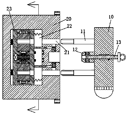
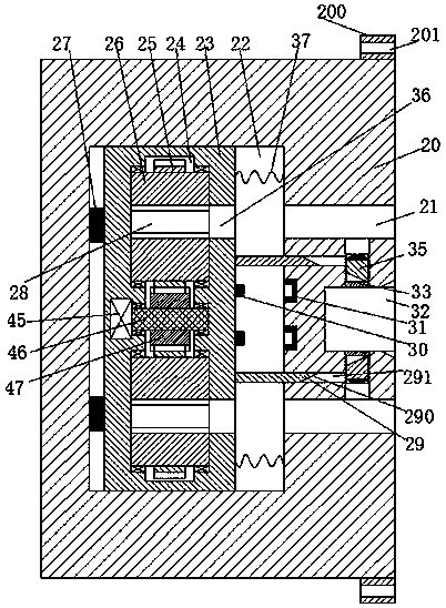
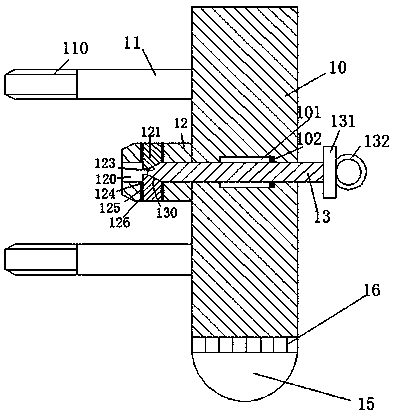
[0032] Such as Figure 1-8As shown, an energy-saving lamp device of the device of the present invention includes a lamp base part 20 and a lamp part 10 used in conjunction with the lamp base part 20, and the lamp base part 20 is provided with a sliding cavity 22, the The first insertion hole 21 communicating with the outer end is provided in the right end wall of the sliding chamber 22, and a sliding frame 23 is installed in the sliding chamb...


PUM


Abstract

The invention discloses an energy-saving lamp device. The energy-saving lamp device comprises a lamp holder part and a lamp head part used in cooperation with the lamp holder part. A sliding cavity isformed in the lamp holder part, first plug-in holes communicated with the outer end are formed in the right end wall of the sliding cavity, a sliding frame sliding in the left and right directions ismounted in the sliding cavity, and first compression springs abutting against the right end wall of the sliding cavity are arranged at the right end of the sliding frame. A placement groove extendingupwards and downwards is formed in the sliding frame, vertically and symmetrically arranged shaft sleeves are rotatably mounted in the placement groove, spiral grooves which are horizontally communicated are formed in the shaft sleeves, and second plug-in holes communicated with the sliding cavity are formed in the right end wall of the placement groove. Second toothed wheels are fixedly mountedon the outer circumferences of the shaft sleeves, first toothed wheels cooperatively connected with the second toothed wheels are also rotatably installed between the two shaft sleeves through a rotary pin shaft, and the rotary pin shaft is connected to a motor fixedly installed at the center of the left end wall of the placement groove.

Description

technical field [0001] The invention relates to the field of energy-saving lamps, in particular to an energy-saving lamp device. Background technique [0002] In modern home life, plug-in energy-saving lamps are often installed near the bedside of the bedroom for night lighting. The traditional plug-in energy-saving lamp setting mode is too simple, and the plug-in between the lamp head and the lamp holder is only achieved by friction. state, but this locking method is extremely unstable, often due to accidental human touch or self-weight, etc., causing loose plugs or falling lights, which has great disadvantages. At the same time, because the lamp holder of the energy-saving lamp is generally They are all set near the head of the bed and are directly charged. For some people who lack safety awareness (such as young children), when a metal rod is inserted into the lamp holder and contacts the conductive part, it will cause an electric shock accident. , will cause death in se...

Claims


Application Information

Patent Timeline
Patent Type & Authority Applications(China)
IPC IPC(8): F21S8/00F21V23/06F21V21/002F21Y115/10
CPCF21S8/035F21V21/002F21V23/06F21Y2115/10
Inventor 陈安娜
Owner 俞岳田
Why Eureka
Try Eureka