A Method for Measuring Stiffness Coefficient of Cracked Rotor

A technology of stiffness coefficient and measurement method, which is applied in the field of measurement of the stiffness coefficient of cracked rotors, can solve the problems of difficulty in measuring the stiffness coefficient of the rotor, and it is difficult to paste the crack tip of the strain gauge, so as to avoid singularity problems, low cost and simple method. Effect

Active Publication Date: 2019-08-30
HEFEI UNIV OF TECH
View PDF6 Cites 2 Cited by
  • Summary
  • Abstract
  • Description
  • Claims
  • Application Information

AI Technical Summary

Problems solved by technology

For the measurement of the stiffness coefficient of the cracked rotor, it is difficult to accurately measure the stiffness coefficient of the rotor directly at the crack cross-section due to the difficulty of pasting the strain gauge at the position of the crack cross-section and the singularity of the crack tip

Method used


Image

  • A Method for Measuring Stiffness Coefficient of Cracked Rotor
  • A Method for Measuring Stiffness Coefficient of Cracked Rotor
  • A Method for Measuring Stiffness Coefficient of Cracked Rotor

Examples


Embodiment Construction

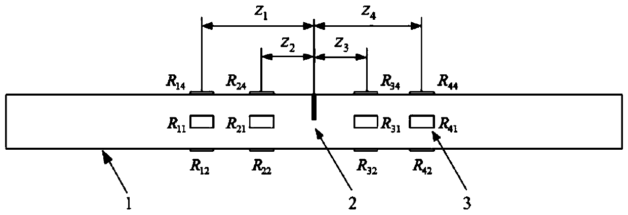
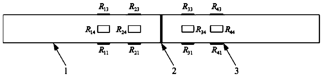
[0039] see figure 1 with figure 2 , the measurement method of cracked rotor stiffness coefficient in this embodiment is:

[0040] On the cracked rotor 1, four axial measurement positions are arranged along the axial direction of the cracked rotor 1, and the four axial measurement positions are distributed in pairs on both sides of the crack 2; Four measuring points are distributed, and strain gauges are pasted on each measuring point, and a total of sixteen strain gauges R are pasted ij, i=1,2,3,4; j=1,2,3,4; among them, R i2 and R i4 is the strain gauge at the i-th axial measurement position and at a pair of measurement points along the direction of the crack opening; R i1 and R i3 is the strain gauge at a pair of measuring points at the i-th axial measuring position, which are also in the direction perpendicular to the crack opening; and R 11 , R 21 , R 31 and R 41 co-located on the same straight line, R 13 , R 23 , R 33 and R 43 co-located on the same straight...


PUM


Abstract

The invention discloses a crack rotor stiffness coefficient measuring method. According to the method, four measurement positions are arranged around a crack damage position along an axial direction;four strain gauges are evenly attached to each measurement position along a circumferential direction; a strain gauge is attached onto a non-bearing structure made the same material as a rotor and isused for eliminating the temperature effect of the strain gauges; the radius of curvature of the bending of the rotor is calculated according to a relation between strain and radius of curvature undera beam bending condition; the radius of curvature is fitted through adopting a cubic function, so that the radius of curvature of the rotor at the crack position is obtained; the stiffness coefficient of the cracked rotor is calculated according to a relationship between cross-section bending moment and the radius of curvature and anti-bending stiffness; and therefore, the stiffness coefficientsof the rotor at different rotation angles can be measured. With the method of the invention adopted, a basis can be provided for verifying the accuracy of a crack model, and an effective means is alsoprovided for the dynamic modeling of the cracked rotor.

Description

technical field [0001] The invention belongs to the field of structural dynamic testing, and in particular relates to a method for measuring the stiffness coefficient of a cracked rotor. Background technique [0002] Rotating machinery is an important equipment widely used in petrochemical, steel, electric power, aerospace and other national economic lifeline industries. Once these equipment fail due to unplanned downtime or major accidents, it will bring huge economic losses and harm to the society. Large-scale rotating machinery operates under complex and harsh conditions such as high speed, heavy load, high temperature, high pressure, fatigue, and corrosion for a long time. Fatigue cracks will inevitably occur on the rotor, and crack failures are also common faults in rotating machinery. For large rotating machinery operating at high speed, if cracks cannot be detected in time, the normal function of the equipment will be affected at least, and the tragedy of machine cras...

Claims


Application Information

Patent Timeline
Patent Type & Authority Patents(China)
IPC IPC(8): G01M5/00G01N19/08
Inventor 王帅毕传兴郑昌军张小正张永斌徐亮
Owner HEFEI UNIV OF TECH
Why Eureka
Try Eureka