Timing switch applicable to various switches

A timing switch and switch technology, applied in the field of switches, can solve the problems of high cost of timing function, inconvenient adsorption, small space and other problems

Inactive Publication Date: 2018-05-15
CHENGDU KECHUANGCHENG TECH
View PDF4 Cites 0 Cited by
  • Summary
  • Abstract
  • Description
  • Claims
  • Application Information

AI Technical Summary

Problems solved by technology

[0004] Based on the above technical problems, the present invention provides a timing switch suitable for a variety of switches, thereby solving the problem that the existing toilet exhaust fans and other electrical appliances have high cost of timing functions, and

Method used


Image

  • Timing switch applicable to various switches
  • Timing switch applicable to various switches
  • Timing switch applicable to various switches

Examples


Embodiment 1

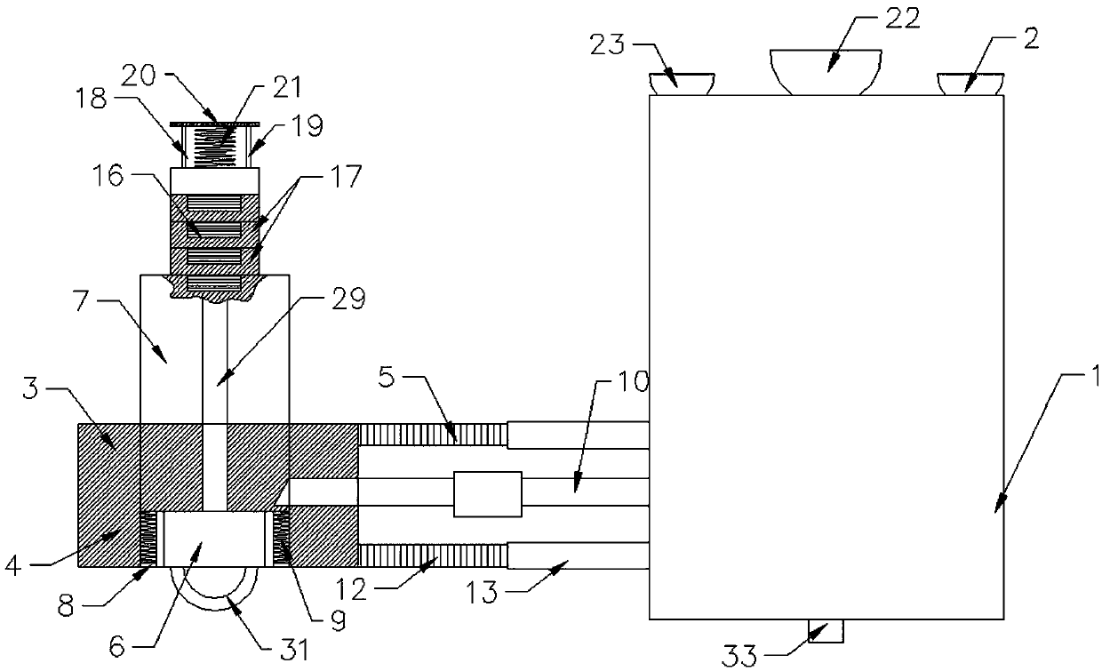
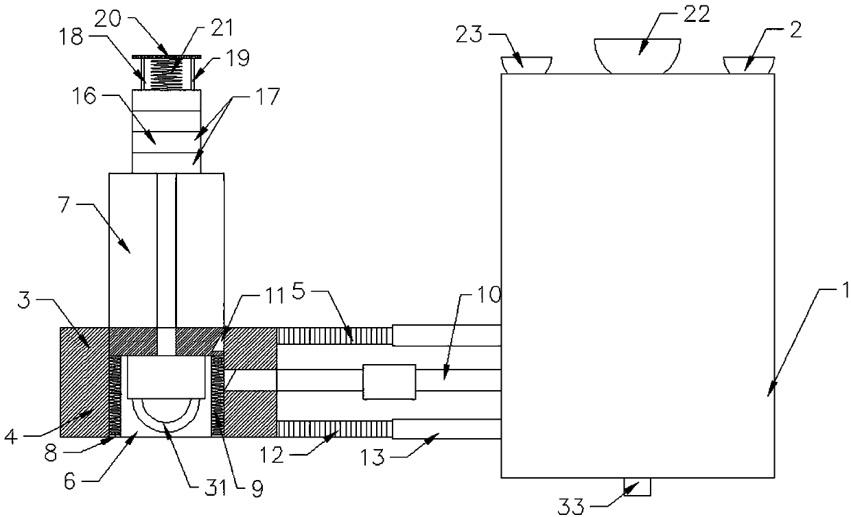
[0044] A timer switch suitable for various switches, comprising a timer switch body 1, an adsorption device 2 for connecting to a wall is arranged on the rear side of the timer switch body 1, and a switch device 3 is arranged on one side of the timer switch body 1;

[0045] The switch device 3 includes a base 4, a connecting rod 5 is horizontally arranged between the base 4 and the timing switch body 1, and a through hole 6 is arranged inside the base 4, and the base 4 is located at the position of the through hole 6 and is provided with a hole suitable for the through hole 6. Equipped with a push-pull rod 7, the side of the base 4 away from the adsorption device 2 is located inside the through hole 6 with an annular baffle 8, and a first spring 9 is provided between the baffle 8 and the push-pull rod 7;

[0046] A crossbar 10 is arranged between the push-pull rod 7 and the timing switch body 1, and the timing switch body 1 controls the crossbar 10 to move in the horizontal dir...

Embodiment 2

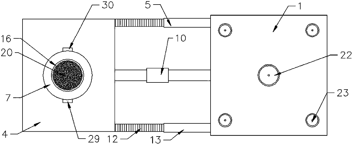
[0052] This embodiment is further optimized based on Embodiment 1. The outer wall of the push-pull rod 7 is evenly distributed with a plurality of guide rods 29 parallel to the length direction of the push-pull rod 7. The base 4 is provided with a guide groove 30 corresponding to the position of the guide rod 29, and the guide rod 29 And the guide groove 30 can not only guide the push-pull rod 7 during the movement of the push-pull rod 7, but also prevent the push-pull rod 7 from rotating, so as to facilitate the connection of the groove 11 and the cross bar 10.

Embodiment 3

[0054] This embodiment is further optimized based on Embodiment 1. The push-pull rod 7 is provided with a pull ring 31 on one side of the first spring 9, so that the push-pull rod 7 can be stretched conveniently.


PUM


Abstract

The invention belongs to the switch technical field and discloses a timing switch applicable to various switches. The timing switch includes a timing switch body, an adsorption device and a switch device; the switch device comprises a base; a connecting rod is arranged between the base and the timing switch body; the base is provided with a push-pull rod; a cross bar matched with the push-pull rodis arranged between the push-pull rod and the timing switch body; the connecting rod includes an adjusting rod and an adjusting cylinder in threaded connection with the adjusting rod; and the cross rod includes daughter rods arranged at two ends of the cross rod and a mother rod arranged between the two daughter rods. The timing switch of the invention has the advantages of simple structure and low cost, can be used to control a plurality of devices and is convenient to assemble and disassemble; and the length of the timing switch can be adjusted through the connecting rod and the cross rod,so that a distance between the adsorption device and the switch device can be adjusted, and therefore, failure to use the timing switch which is caused by insufficient space beside the timing switch which is further caused by the incapability of changing the length of the connecting rod can be avoided.

Description

technical field [0001] The invention relates to the technical field of switches, in particular to a timing switch suitable for various switches. Background technique [0002] At present, in the bathrooms of urban housing, exhaust fans are installed in the bathrooms for the convenience of discharging the odor from the bathrooms, but most of the exhaust fans are manual switches. The exhaust fan is turned off, and people usually forget to turn off the exhaust fan when they are busy with other things after going to the toilet, resulting in energy waste; since people usually go to sleep directly after going to the toilet at night, the exhaust fan cannot be turned on at this time The air fan has become a headache. If it is turned on, it can only be turned off in the morning, resulting in a waste of energy; if it is not turned on, when other people go to the toilet, the smell in the bathroom will be stinky, making others miserable; [0003] There is also a switch that controls the...

Claims


Application Information

Patent Timeline
IPC IPC(8): H01H43/02H01H43/04
CPCH01H43/02H01H43/022H01H43/04
Inventor 雍海燕
Owner CHENGDU KECHUANGCHENG TECH
Why Eureka
Try Eureka