Time-inversion super-resolution pipeline leakage monitoring method

A time-reversal and super-resolution technology, applied in the application of electrical devices to test fluid tightness, etc., can solve the problem of low practicability

Active Publication Date: 2018-06-05
DONGGUAN UNIV OF TECH
View PDF5 Cites 4 Cited by
  • Summary
  • Abstract
  • Description
  • Claims
  • Application Information

AI Technical Summary

Problems solved by technology

Therefore, the practicability of exi

Method used


Image

  • Time-inversion super-resolution pipeline leakage monitoring method
  • Time-inversion super-resolution pipeline leakage monitoring method
  • Time-inversion super-resolution pipeline leakage monitoring method

Examples


Embodiment Construction

[0091] The present invention will be further described below in conjunction with accompanying drawing:

[0092] The present invention comprises the following steps:

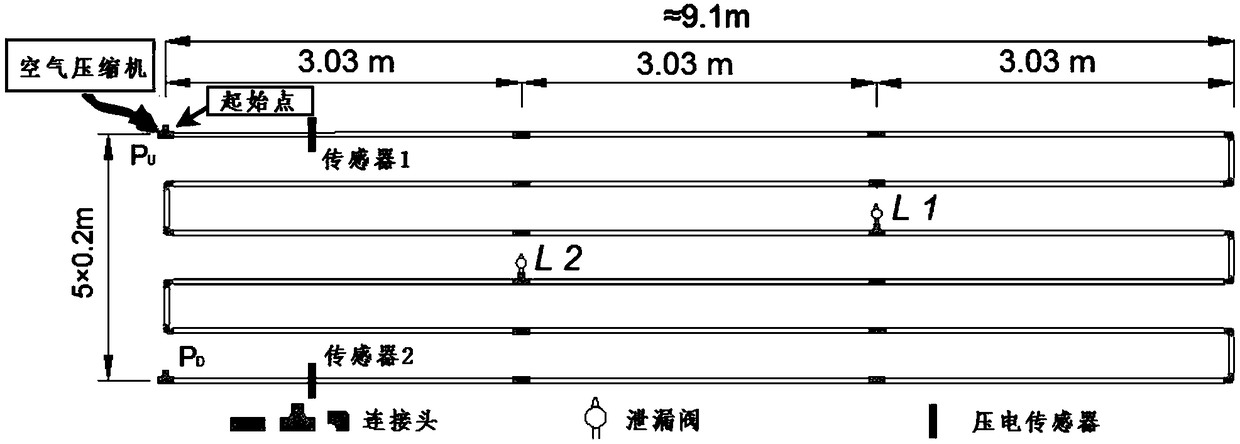
[0093] Two piezoelectric sensors, namely piezoelectric sensor 1 and piezoelectric sensor 2, are placed at both ends of the gas pipeline to detect the negative pressure wave signal generated during leakage; the leak point is located at r L , the negative pressure wave signal generated by the leak is e(r L ,t); let r L and r n The channel impulse response function between

[0094] h m (r n ,r L ,t)=a n,L,m δ(t-t n,L,m ) (1)

[0095] Among them, a n,L,m for r L and r n The signal attenuation coefficient between, δ(t-t n,L,m ) is the impulse signal, t n,L,m for the negative pressure wave at r L and r n The propagation time between , the symbol "m" represents the corresponding function obtained by measurement;

[0096] Then, at r n The negative pressure wave signal received by the n-th sensor is expr...


PUM


Abstract

The invention discloses a time-inversion super-resolution pipeline leakage monitoring method. Compared with the prior art, the invention has the advantages as follows: in allusion to the defect that ametamaterial component is required to be used near a signal source for achieving super-resolution imaging positioning in a conventional scheme, a time-inversion super-resolution time domain adjustment function is provided and designed, and through adjustment of the function, the resolution can be increased and a resolution diffraction limit can be broken through. By the time-inversion super-resolution pipeline leakage monitoring method, super-resolution is achieved by an algorithm and the metamaterial component is not required to be used, so that the time-inversion super-resolution pipeline leakage monitoring method has higher practicality and lower cost than the conventional time-reversion super-resolution imaging positioning scheme. Therefore, by using the novel technology, low-cost andsuperhigh-resolution leakage monitoring of a long-distance gas pipeline can be achieved.

Description

technical field [0001] The invention relates to the field of industrial detection, in particular to a time-reversal super-resolution pipeline leakage monitoring method. Background technique [0002] When the gas pipeline leaks, a negative pressure wave signal will be generated. By capturing the signal with a piezoelectric sensor and processing it with an algorithm, the location information of the leak point can be obtained. However, limited by the diffraction limit, the positioning resolution is often greater than one-half wavelength, that is, the -3dB region of the target image is not less than one-half wavelength. Due to the low frequency and large wavelength of the negative pressure wave, the existing positioning technology often has a low resolution when calculating the position of the leak point, which leads to a great reduction in the accuracy of positioning, and it is difficult to accurately monitor the situation of the leak area. evaluation of. [0003] Gas pipelin...

Claims


Application Information

Patent Timeline
IPC IPC(8): G01M3/40
CPCG01M3/40
Inventor 张光旻宋钢兵宋跃郑愚李钊勤
Owner DONGGUAN UNIV OF TECH
Why Eureka
Try Eureka