Supercharge Your Innovation With Domain-Expert AI Agents!

Firm bridge device

A bridge and firm technology, applied in the parts, electrical components, coupling devices and other directions of connecting devices, can solve the problems of shortened service life of electrical facilities, electric shock accidents at the connecting terminals, unstable power supply connections, etc., so as to reduce electric shock accidents. , the effect of safe and stable power supply and low production cost

Inactive Publication Date: 2018-06-05
广西南宁旭兆建筑工程技术有限公司
View PDF1 Cites 0 Cited by
  • Summary
  • Abstract
  • Description
  • Claims
  • Application Information

AI Technical Summary

Problems solved by technology

[0002] At present, the construction of bridges is inseparable from electrical facilities. The use of electrical facilities requires that the electrical terminals be inserted into the electrical bases to be powered on before they can be used. The electrical terminals of electrical facilities can be directly inserted into the power supply holes of the electrical bases. Although this plug-in method is very convenient to operate, the length of the cables between the power terminal and the electrical equipment is different. When in use, the cables are often placed randomly. If someone accidentally makes a mistake If the kick hits the cable by mistake, it will cause the power connection terminal to be directly disconnected from the matching connection with the power supply hole of the power connection seat, which will lead to a sudden power failure of the electrical facilities, so that the service life of the electrical facilities will be reduced. It will directly cause the burning of electrical facilities. Therefore, the existing plugging method between the power supply terminal and the power supply tank has potential safety hazards of unstable power supply connection, and the existing power supply terminal is easy to cause electric shock during the plugging process. ACCIDENT

Method used


Image

  • Firm bridge device
  • Firm bridge device
  • Firm bridge device

Examples


Embodiment Construction

[0021] The preferred embodiments of the present invention will be described in detail below in conjunction with the accompanying drawings, so that the advantages and features of the present invention can be more easily understood by those skilled in the art, so as to define the protection scope of the present invention more clearly.

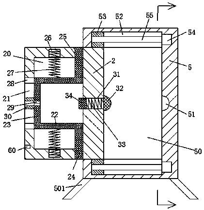
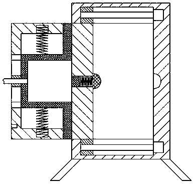
[0022] refer to Figure 1-6 The shown solid bridge equipment includes a power connection base 5 and a power connection terminal 1 connected to electrical equipment through a cable 11, and the bottom of the power connection base 5 is fixedly installed around the foot column 501, and the foot column The bottom of 501 is inclined outward, and the electrical connection seat 5 is provided with a sliding connection groove 50 with the mouth facing left. The middle point of the right end wall is provided with an electrical interface 51, and the first sliding joint groove 52 is provided on the front and rear walls of the sliding joint groove 50. The firs...


PUM


Abstract

The invention discloses a firm bridge device comprising a power supply seat and a power supply head connected to an electric appliance through a cable. Foot columns are fixedly installed on the four sides of the bottom of the power supply seat. The bottoms of the foot columns are inclined outwards. The power supply seat is provided therein with a sliding groove with a mouth facing left. A slidingplate is arranged in the sliding groove movably left and right. An electric interface is arranged at the middle point of the right end wall of the sliding groove. First sliding grooves are disposed onthe front and rear end walls of the sliding groove correspondingly. Protruding heads are arranged on the right sides of the front and the rear end surfaces of the sliding plate and movably cooperatewith the first sliding grooves. The firm bridge device is simple in overall structure, low in production cost, safe and stable in power supply, reduces the electric shock accidents in the constructionprocess of the bridge, and avoids power outage accidents of the electric appliance due to accidental kicking and accidental collision. The power supply head is safe and reliable in locking and the firm bridge device is simple and convenient to operate.

Description

technical field [0001] The invention relates to the field of bridges, in particular to a firm bridge device. Background technique [0002] At present, the construction of bridges is inseparable from electrical facilities. The use of electrical facilities requires that the electrical terminals be inserted into the electrical bases to be powered on before they can be used. The electrical terminals of electrical facilities can be directly inserted into the power supply holes of the electrical bases. Although this plug-in method is very convenient to operate, the length of the cables between the power terminal and the electrical equipment is different. When in use, the cables are often placed randomly. If someone accidentally makes a mistake If the kick hits the cable by mistake, it will cause the power connection terminal to be directly disconnected from the matching connection with the power supply hole of the power connection seat, which will lead to a sudden power failure of...

Claims


Application Information

Patent Timeline
Patent Type & Authority Applications(China)
IPC IPC(8): H01R13/627H01R13/629H01R13/703
CPCH01R13/6275H01R13/629H01R13/7035
Inventor 厉炳炳
Owner 广西南宁旭兆建筑工程技术有限公司
Features
  • R&D
  • Intellectual Property
  • Life Sciences
  • Materials
  • Tech Scout
  • Unparalleled Data Quality
  • Higher Quality Content
  • 60% Fewer Hallucinations
Learn More