Power supply plug assembly

A technology for power supply plug-in and assembly, which is applied to electrical components, parts and circuits of connecting devices, etc., can solve the problems of exposed power supply slots, electric shock accidents, and burning of electrical equipment, so as to increase the safety of use and prevent electric shock accidents. , The effect of safe and stable power supply

Inactive Publication Date: 2017-09-15
陈光才
View PDF4 Cites 10 Cited by
  • Summary
  • Abstract
  • Description
  • Claims
  • Application Information

AI Technical Summary

Problems solved by technology

[0002] At present, the power-on use of electrical equipment is to directly insert the plug connected to it into the power supply groove of the power supply socket and then power it on. The length of the line between the plug and the electrical equipment is different, and there is no other locking device to lock the plug after the plug is inserted into the power supply slot. As a result, the sudden power failure of the electrical equipment will result in a reduction in the service life of the electrical equipment, and in serious cases, it will directly cause the burning of the electrical equipment. The connection is unstable. In addition, when the electrical equipment is not in use, the plug is often pulled out from the power supply tank, which will cause the power supply tank to be exposed. If there are children in the family who directly insert their fingers or metal rods into the power supply socket In the power supply tank, this will cause electric shock accidents, and even cause life-threatening danger to children, which poses a great safety hazard

Method used


Image

  • Power supply plug assembly
  • Power supply plug assembly
  • Power supply plug assembly

Examples


Embodiment Construction

[0020] The preferred embodiments of the present invention will be described in detail below in conjunction with the accompanying drawings, so that the advantages and features of the present invention can be more easily understood by those skilled in the art, so as to define the protection scope of the present invention more clearly.

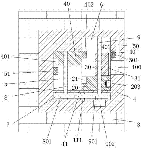
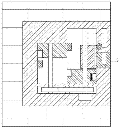
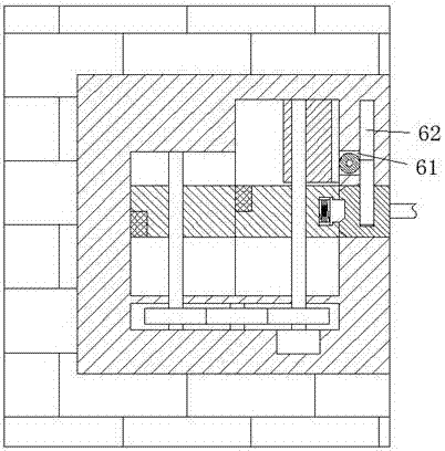
[0021] refer to Figure 1-6The power supply plug assembly shown includes a power supply part 4 arranged in a wall 3 and a plug part 10 for plugging and electrically mating connection with the power supply part 4. The power supply part 4 includes a base 4 and a The left sliding chamber 5 arranged in the base 4 and the right sliding chamber 6 communicating with the left sliding chamber 5, the base 4 below the left sliding chamber 5 and the right sliding chamber 6 are provided with Gear cavity 7, the center of the right end wall of the right sliding cavity 6 is provided with a slot 100 communicating with the outside of the base 4, and the upper end ...


PUM


Abstract

The invention discloses a power supply plug assembly, which comprises a power supply part arranged in the wall and a plug part for plugging and electrically matching connection with the power supply part, the power supply part includes a base and a The left sliding chamber in the seat and the right sliding chamber communicated with the left sliding chamber, a gear chamber is arranged in the base below the left sliding chamber and the right sliding chamber, and the center of the right end wall of the right sliding chamber There is a slot communicating with the outside of the base, and an upwardly extending lock chute is provided in the upper end wall of the slot, and the lock chute above the slot communicates with the right sliding cavity There are slots, and a left sliding block can be slid up and down in the left sliding cavity; the invention has simple structure, low production cost, safe and stable power supply, effectively eliminates the invention of electric shock accidents in existing life, and ensures people's safety. Life is safe, and the plug-in and power-on operation is more convenient, which meets the existing use requirements of plug-in and power-on.

Description

technical field [0001] The invention relates to the field of power supply, in particular to a power supply plug assembly. Background technique [0002] At present, the power-on use of electrical equipment is to directly insert the plug connected to it into the power supply groove of the power supply socket and then power it on. The length of the line between the plug and the electrical equipment is different, and there is no other locking device to lock the plug after the plug is inserted into the power supply slot. As a result, the sudden power failure of the electrical equipment will result in a reduction in the service life of the electrical equipment, and in serious cases, it will directly cause the burning of the electrical equipment. The connection is unstable. In addition, when the electrical equipment is not in use, the plug is often pulled out from the power supply tank, which will cause the power supply tank to be exposed. If there are children in the family who d...

Claims


Application Information

Patent Timeline
Patent Type & Authority Applications(China)
IPC IPC(8): H01R13/447H01R13/639H01R13/71
CPCH01R13/447H01R13/639H01R13/71
Inventor 陈光才
Owner 陈光才
Why Eureka
Try Eureka