
Connector for measurement of electric resistance, connector device for measurement of electric resistance and production process thereof, and measuring apparatus and measuring method of electric resis

A technology for measuring resistance and resistance measurement, applied in the direction of measuring resistance/reactance/impedance, measuring devices, measuring electrical variables, etc., can solve problems such as large measurement error range and difficult circuit board resistance measurement

Inactive Publication Date: 2006-04-26
JSR CORPORATIOON
View PDF2 Cites 13 Cited by
  • Summary
  • Abstract
  • Description
  • Claims
  • Application Information

AI Technical Summary

Problems solved by technology

[0013] Since this resistance measuring device is a measuring device according to the so-called pseudo-four-probe method, however, the measurement error range is large, making it difficult to perform resistance measurement for a circuit board with low resistance between electrodes with high precision.

Method used


Image

  • Connector for measurement of electric resistance, connector device for measurement of electric resistance and production process thereof, and measuring apparatus and measuring method of electric resis
  • Connector for measurement of electric resistance, connector device for measurement of electric resistance and production process thereof, and measuring apparatus and measuring method of electric resis
  • Connector for measurement of electric resistance, connector device for measurement of electric resistance and production process thereof, and measuring apparatus and measuring method of electric resis

Examples


Embodiment Construction

[0178] Hereinafter, embodiments of the present invention will be described in detail.

[0179]

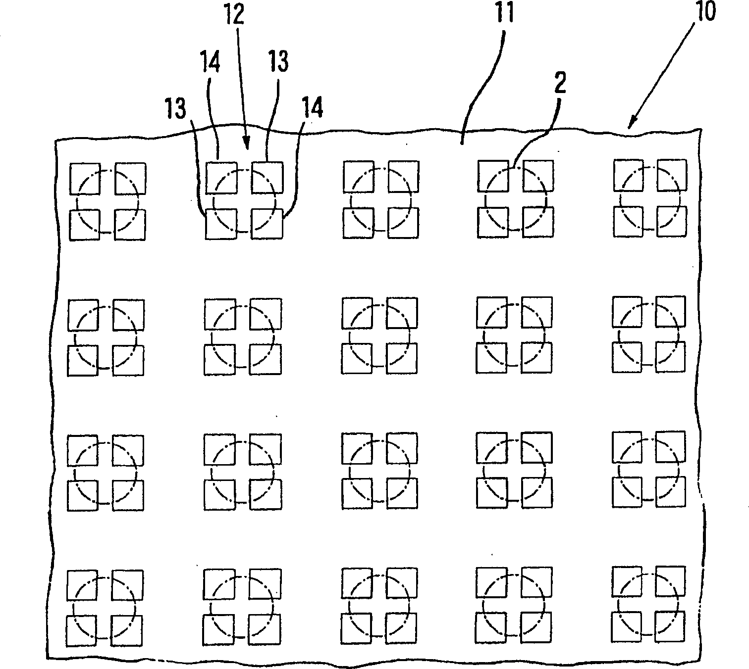
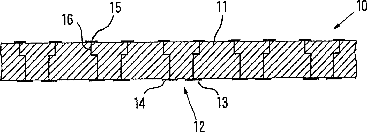
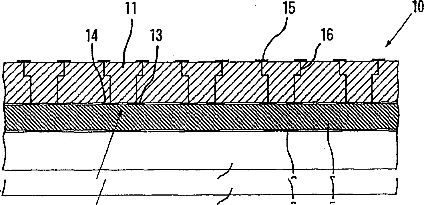
[0180] figure 1 is a plan view illustrating a connector for measuring resistance according to a first embodiment of the present invention, and figure 2 is a sectional view illustrating the structure of a connector for measuring resistance according to the first embodiment.

[0181] According to the first embodiment, the connector 10 for measuring resistance has an insulating substrate 11 . On the front surface of the insulating substrate 11, according to a pattern corresponding to a pattern (indicated by alternating short and long dashed lines) of one surface-side electrode 2 to be inspected formed on one surface of the circuit board whose resistance is to be measured, arranged A plurality of electrode groups 12 are connected. These connecting electrode sets 12 are respectively composed of a total of 4 electrodes, 2 rectangular electrodes 13 for current supply and 2 rectangu...


PUM


Abstract

Disclosed herein are a connector for measuring resistance, a connector device for measuring resistance and a manufacturing method thereof, and a measuring device and method for circuit boards, by which even when the area of ​​the circuit board to be inspected Even when there are multiple electrodes to be inspected that are small in size, the necessary electrical connections must also be made, and the desired resistance measurement must be performed with high precision. According to the present invention, a connector for measuring resistance includes an insulating substrate and is arranged on the front surface of the insulating substrate according to a pattern corresponding to a pattern of a plurality of electrodes to be inspected in a circuit board to be inspected whose resistance is to be measured. multiple connected electrode sets. Each of the above-mentioned connecting electrode groups is composed of at least 3 electrodes of an electrode for current supply and an electrode for voltage measurement arranged separately from each other, at least one of these electrodes is an electrode for current supply, and at least one of is the electrode used for voltage measurement.

Description

technical field [0001] The present invention relates to a connector for measuring resistance, a connector device for measuring resistance and a production method thereof, and a measuring device and method for measuring resistance of a circuit board. Background technique [0002] In recent years, with the need to speed up signal transmission in electronic parts and electronic equipment incorporating such parts, wiring between electrodes with low resistance is required to be developed for making LSI packages such as BGA and CSP or mounting these semiconductor devices circuit board. Therefore, in the electrical inspection of a circuit board, it is very important to measure the resistance of wiring between electrodes of such a circuit board with high precision. [0003] In the process of measuring the resistance of the circuit board, therefore, for example, a four-probe method is employed, in which the probes PA and PD for current and the probes PB and PC for voltage measuremen...

Claims


Application Information

Patent Timeline
Patent Type & Authority Applications(China)
IPC IPC(8): G01R1/073G01R31/28
CPCG01R1/07314G01R1/07378G01R31/2831G01R1/073G01R27/00
Inventor 木村洁下田杉郎原富士雄
Owner JSR CORPORATIOON
Learn More