Battery component of new-energy electric automobile

A technology for battery components and electric vehicles, applied in electric vehicle charging technology, electric vehicles, battery pack components, etc., can solve the problems of increasing the economic burden of vehicle owners and difficult to achieve dense coverage of charging sites.

Inactive Publication Date: 2018-10-30
JIANGSU CERA THERMAL TECH
View PDF9 Cites 13 Cited by
  • Summary
  • Abstract
  • Description
  • Claims
  • Application Information

AI Technical Summary

Problems solved by technology

[0004] The above solution provides a solution that uses robots to automatically replace batteries, but this requires corresponding automated charging stations, and it is difficult to achieve d

Method used


Image

  • Battery component of new-energy electric automobile
  • Battery component of new-energy electric automobile
  • Battery component of new-energy electric automobile

Examples


Embodiment 1

[0058] according to Figure 1 to Figure 12 As shown, this embodiment is a new energy electric vehicle battery assembly, including a battery case 2 with an upper end opening, a case cover 21 fixedly connected to the upper end of the battery case, and a battery case installed on the battery case and the case cover. A lithium battery (not shown) in the space between the boards.

[0059] Electric mortise locks 4 are respectively installed on the side walls of the two long sides near the front and rear ends of the battery housing, and the inner wall of the battery installation groove corresponds to the position of each electric mortise lock. fixed jack T1.

[0060] The middle position of the bottom of the battery housing is formed with a circular mobile vehicle installation cavity 22 with the opening facing downwards, and a mobile vehicle 5 for moving the battery assembly is installed in rotation at the lower end of the mobile vehicle installation cavity.

[0061] The mobile vehi...

Embodiment 2

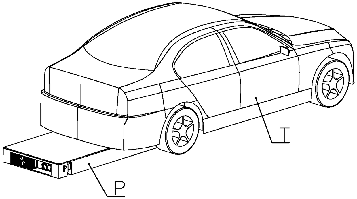
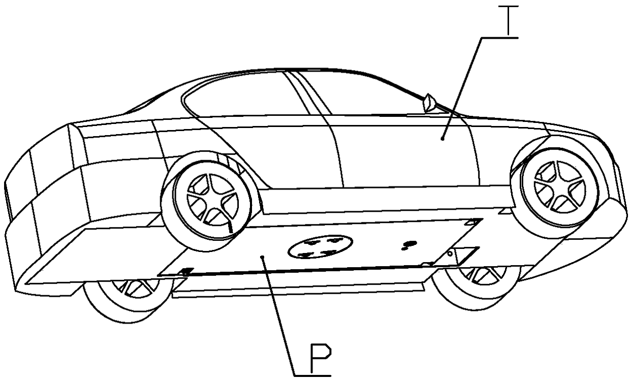
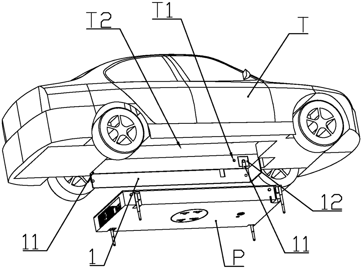
[0076] according to Figure 1 to Figure 12 As shown, this embodiment is a new energy electric vehicle using the battery assembly of Embodiment 1, including a vehicle body T, and a battery assembly P in the shape of a rectangular sheet is detachably installed at the lower end of the vehicle body.

[0077] The lower end of the vehicle body is provided with a battery installation groove T2 for accommodating the battery assembly, and a battery installation slot T2 is installed on the left side of the battery installation groove along the length direction of the vehicle body for connecting the battery assembly and the battery assembly when the battery assembly is installed in the battery installation groove. The positioning baffle 1 aligned with the battery installation slot.

[0078]The front end of the left side wall in the battery installation groove is equipped with a baffle motor 12 that drives the positioning baffle to extend or retract; the two ends of the positioning baffle...

Embodiment 3

[0106] This embodiment makes the following improvements on the basis of Embodiment 1 or 2: an upper connection capacitor cavity 211 is formed on the cover plate of the housing at a position different from that of the mobile car, and an upper connection capacitor cavity 211 is slidably installed in the upper connection capacitor cavity. Electric connection seat 6, described upper connection electric seat upper end is equipped with 2-3 ring-shaped upper connection electric electrodes 61 concentrically arranged; In the middle of described upper connection electric seat upper end, electric connection permanent magnet 62 is installed; The outer wall of the lower part of the seat is connected with more than two limit heads 63, and the side wall of the upper connection capacitor cavity is formed with a sliding limit groove 2112 that is slidably connected with each of the limit heads; the side wall of the upper connection capacitor cavity is also formed There is a connection port 2111,...


PUM


Abstract

The invention discloses a battery component of a new-energy electric automobile. The battery component is detachably installed at the lower end of an automobile body of the electric automobile; a battery installing groove for containing the battery component is formed in the lower end of the automobile body, and a positioning baffle is installed in the battery installing groove along the left sideof the automobile body in the length direction, and makes the battery component aligned with the battery installing groove when the battery component is installed in the battery installing groove. Byarranging a movable trolley at the lower end of the battery component, the battery component can move under remote control when separating from the automobile body; in addition, vertically-arranged electric pushing rods are installed on the two sides of the battery component, and in this way, when the battery component is installed on the automobile body, the battery component can be lifted intothe battery installing groove in the bottom of the automobile body only by moving the battery component to the position under the battery installing groove via the movable trolley and then controllingthe electric pushing rods to lengthen.

Description

technical field [0001] The invention belongs to the field of new energy vehicles, and in particular relates to a battery assembly of an electric vehicle that obtains long battery life by quickly replacing batteries. Background technique [0002] The Chinese patent application with document number CN106295932A discloses a battery charging system for electric vehicles. More specifically, the batteries of commercially sold electric vehicles are leased. The battery leasing company also sets up a charging station. , only need to quickly replace the charged battery of the same type with the same type of battery that needs to be charged, which will greatly reduce the waiting time for charging. However, the above-mentioned scheme does not disclose the specific way of replacing the battery, because the storage battery used for electric vehicles is generally heavier, and it is too laborious to operate purely manually. [0003] The Chinese patent with document number CN201825013U disc...

Claims


Application Information

Patent Timeline
IPC IPC(8): B60K1/04B60L11/18H01M2/10H01M2/20H01M10/613H01M10/625H01M10/63H01M10/6551H01M10/6556H01M10/6563H01M10/6568
CPCB60K1/04B60K2001/0438B60K2001/0472B60L50/66B60L58/26H01M2220/20H01M10/613H01M10/625H01M10/63H01M10/6551H01M10/6556H01M10/6563H01M10/6568H01M50/20H01M50/502B60K2001/005B60L50/64B60L53/68B60L53/80H01M10/425H01M10/486H01M10/66H01M50/207H01M50/249H01M50/256H01M50/258H01M50/296Y02E60/10Y02T10/70Y02T10/7072Y02T90/12Y02T90/16Y02T90/167Y04S30/12
Inventor 江桂英
Owner JIANGSU CERA THERMAL TECH
Why Eureka
Try Eureka