Power supply system capable of locking operation

A power supply system and electric power technology, applied in the direction of circuits, electrical components, parts of connecting devices, etc., can solve problems such as burning of electrical equipment, power failure of electrical equipment, different lengths of wires from plugs to electrical equipment, etc., to achieve power supply Safe and stable, the effect of increasing safety

Inactive Publication Date: 2017-12-19
余达辉
View PDF6 Cites 9 Cited by
  • Summary
  • Abstract
  • Description
  • Claims
  • Application Information

AI Technical Summary

Problems solved by technology

[0002] At present, the power-on of electrical equipment is to directly insert the plug connected to it into the power supply hole of the socket to connect the power supply, and the power supply socket and the power supply will always be in the power-on state. The lengths of wires between electrical equipment are different, and there is no other locking device to lock the plug after the plug is inserted into the power supply hole. When the wire is kicked, it will cause the plug to detach from the power supply hole, causing the Sudden power failure may even directly cause the burning of electrical equipment. Therefore, there is a potential safety hazard of unstable power supply connection in the existing cooperation between the plug and the power supply hole. In addition, when the electrical equipment is not in use, the plug It is often pulled out from the power supply hole, which will cause the power supply hole to be exposed. If a child inserts the conductive metal rod directly into the power supply hole, it will cause an electric shock accident and there is a greater safety hazard

Method used


Image

  • Power supply system capable of locking operation
  • Power supply system capable of locking operation
  • Power supply system capable of locking operation

Examples


Embodiment Construction

[0019] The preferred embodiments of the present invention will be described in detail below in conjunction with the accompanying drawings, so that the advantages and features of the present invention can be more easily understood by those skilled in the art, so as to define the protection scope of the present invention more clearly.

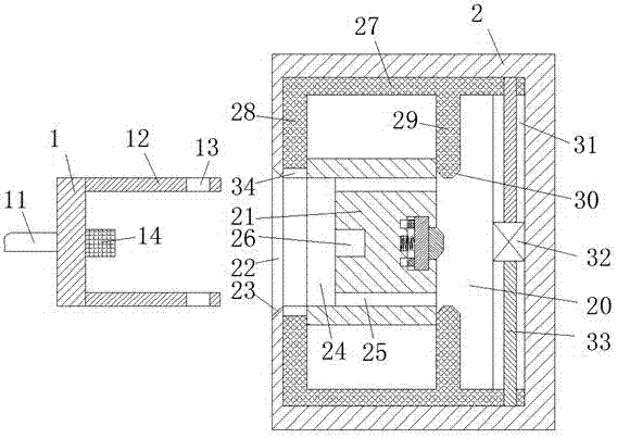
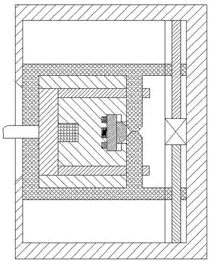
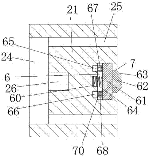
[0020] refer to Figure 1-4 An operably lockable power supply system shown includes a power connection part connected to electrical equipment through wires 11 and a power supply part arranged on the wall. The power connection part includes a push block 1, and the push block Two insertion rods 12 are symmetrically arranged on the front and rear ends of the right end face of 1, and locking perforations 13 are arranged at the right ends of the two insertion rods 12, and a power connector 14 is arranged in the middle of the right end face of the push block 1, and the The power supply part includes a seat body 2, a movable cavity 20 is arranged in the...


PUM


Abstract

The invention discloses a power supply system capable of locking operation. The power supply system comprises a power connection part and a power supply part, wherein the power connection part is connected with power utilization equipment via a wire, the power supply part is arranged on a wall body, the power connection part comprises a push block, two insertion rods are symmetrically arranged at a front end and a rear end of a right end surface of the push block, locking penetrating holes are formed in right ends of the two insertion rods, a power connector is arranged at a middle position of the right end surface of the push block, the power supply part comprises a seat body, a movable cavity is formed in the seat body, and an opening groove is formed in a middle position of a left end surface of the seat body and communicates with the movable cavity. In the whole device, disconnection and energization of the power connector, namely disconnection and energization of power utilization equipment can be completed by working of a motor, the power supply system is simple and convenient to operate, and is good in power supply stability and safe and reliable in running, and matching operation of the power connection and a power supply hole is simple and convenient.

Description

technical field [0001] The invention relates to the field of electric power, in particular to an operably locked electric power supply system. Background technique [0002] At present, the power-on of electrical equipment is to directly insert the plug connected to it into the power supply hole of the socket to connect the power supply, and the power supply socket and the power supply will always be in the power-on state. The lengths of wires between electrical equipment are different, and there is no other locking device to lock the plug after the plug is inserted into the power supply hole. When the wire is kicked, it will cause the plug to detach from the power supply hole, causing the Sudden power failure may even directly cause the burning of electrical equipment. Therefore, there is a potential safety hazard of unstable power supply connection in the existing cooperation between the plug and the power supply hole. In addition, when the electrical equipment is not in us...

Claims


Application Information

Patent Timeline
Patent Type & Authority Applications(China)
IPC IPC(8): H01R13/639H01R13/70
CPCH01R13/639H01R13/701
Inventor 余达辉
Owner 余达辉
Why Eureka
Try Eureka