A method and device for indoor cooling by utilizing roof rainfall

A technology of rainwater and water inlet pipes, which is applied to roofs, roof coverings, roof drainage, etc., can solve the problems of large initial investment and high operating costs, and achieve the effect of increasing water passing capacity and high environmental benefits

Active Publication Date: 2020-01-21
XI'AN UNIVERSITY OF ARCHITECTURE AND TECHNOLOGY +1
View PDF6 Cites 0 Cited by
  • Summary
  • Abstract
  • Description
  • Claims
  • Application Information

AI Technical Summary

Problems solved by technology

[0004] Aiming at the defects and deficiencies in the prior art, the present invention provides a method and device for indoor cooling by utilizing roof rainfall, which overcomes the relatively large initial investment and operating problems when the existing indoor cooling method is applied to a large-space building. high cost defect

Method used


Image

  • A method and device for indoor cooling by utilizing roof rainfall
  • A method and device for indoor cooling by utilizing roof rainfall
  • A method and device for indoor cooling by utilizing roof rainfall

Examples


Embodiment 1

[0055] This embodiment provides a method for indoor cooling using roof rainfall. The method processes roof rainfall, including the following steps: using a rainwater collection unit to collect roof rainfall, and using the collected rainwater to perform multi-stage rainwater treatment through the rainwater treatment unit. After treatment, the treated rainwater is pumped to the roof, and the rainwater pumped to the roof is dispersed on the roof for indoor cooling.

Embodiment 2

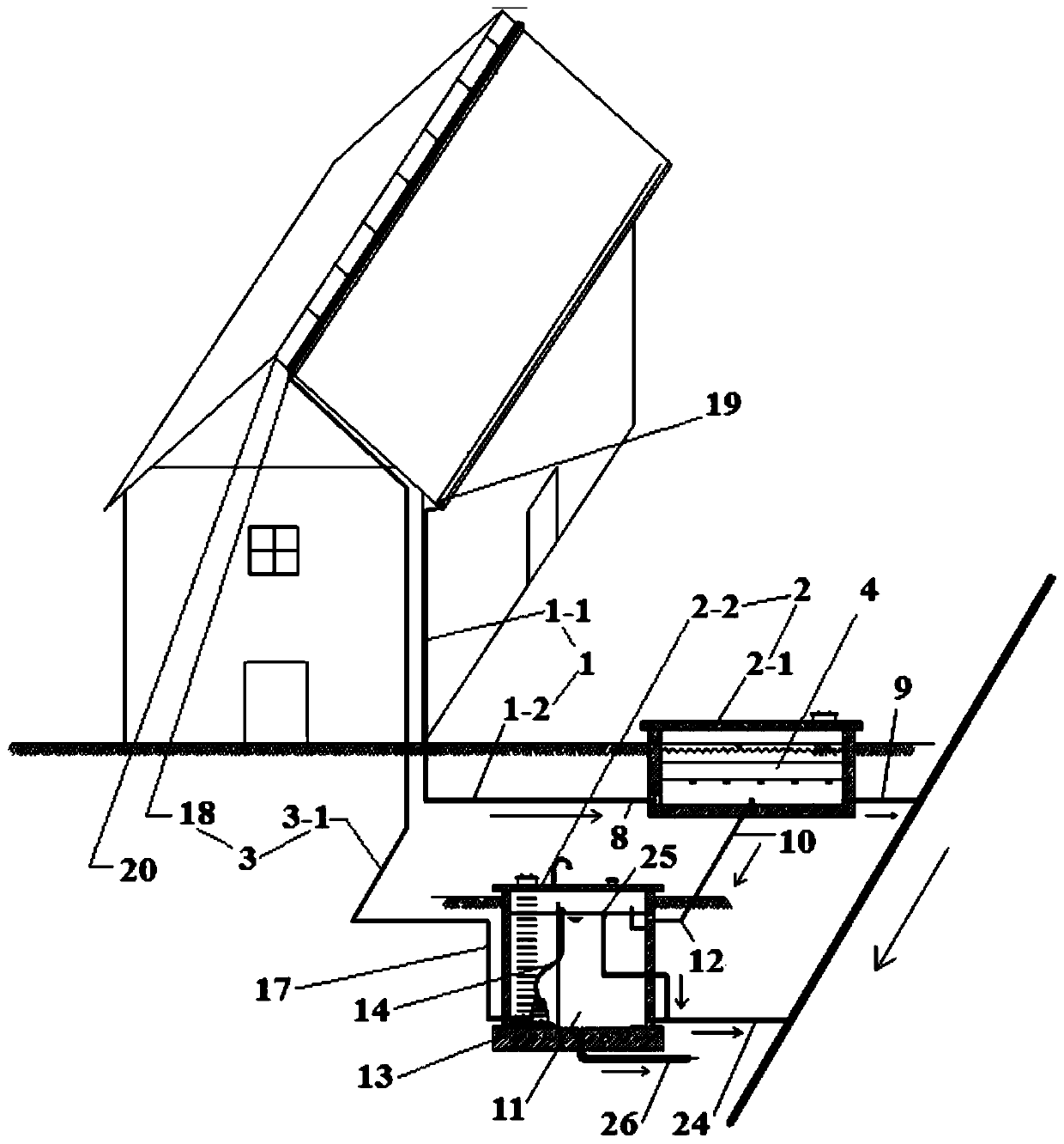
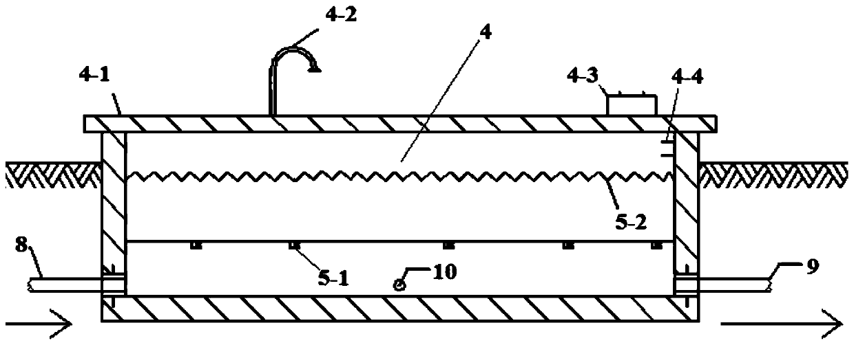
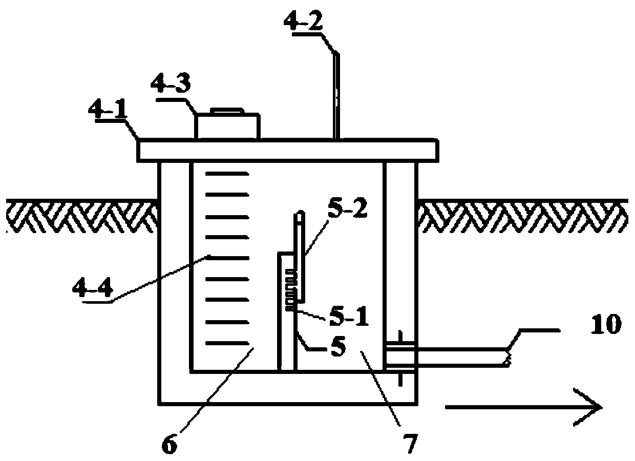
[0057] Such as Figure 1 to Figure 10 As shown, this embodiment provides a device for indoor cooling using roof rainfall, including a rainwater collection unit 1, the rainwater collection unit 1 is connected to a rainwater treatment unit 2, and the rainwater treatment unit 2 is connected to a rainwater delivery unit 3; the rainwater collection unit 1 includes a rainwater collection pipe 1-1, the outlet of the rainwater collection pipe 1-1 is connected to the urban underground drainage network pipe 1-2; the rainwater treatment unit 2 includes a first-level rainwater treatment unit 2-1 and a second-level rainwater treatment unit 2-2 The first-level rainwater treatment unit 2-1 includes a cuboid groove-shaped overflow pool 4, and a partition wall 5 is processed inside the overflow pool 4, and the partition wall 5 divides the overflow pool 4 into a water inlet chamber 6 and an outlet chamber 7, The height of the partition wall 5 is lower than the height of the side wall of the ove...

Embodiment 3

[0063] In this embodiment, on the basis of Embodiment 2, a water inlet buffer plate 21 is installed in the side wall of the static sedimentation tank 11 where the water inlet pipe 12 of the static sedimentation tank is located, and the bottom plate of the water inlet buffer plate 21 is parallel to the bottom of the static sedimentation tank 11 , the height of the bottom plate of the water inlet buffer plate 21 is lower than the height of the static sedimentation tank inlet pipe 12, the length of the water inlet buffer plate 21 is equal to the width of the side wall where the static sedimentation tank water inlet pipe 12 is located, and the side plate of the water inlet buffer plate 21 is perpendicular to the static sedimentation tank. The water inlet pipe 12 of the settling tank is directly opposite to the water inlet pipe 12 of the static settling tank, and a plurality of water inlet holes 21-1 are opened on the side plate of the water inlet buffer plate 21, and enter the stati...


PUM


Abstract

The invention discloses a method and device for indoor cooling by using roof rainfall. In the method, a rainwater collection unit is used to collect roof rainfall, and the collected rainwater is processed by a rainwater treatment unit for multi-stage rainwater treatment, and the treated rainwater is pumped again. To the roof, the rainwater pumped to the roof is dispersed on the roof for indoor cooling; the rainwater collection unit of the device is connected to the rainwater treatment unit, and the rainwater treatment unit is connected to the rainwater delivery unit; the rainwater collection unit includes rainwater collection pipes, and the rainwater treatment unit includes first-level rainwater The processing unit and the secondary rainwater treatment unit, the rainwater conveying unit includes a rainwater conveying pipe, the water inlet of the rainwater conveying pipe is connected to the pressurized water pipe, and the water outlet of the rainwater conveying pipe is connected to a leaking pipe. The invention aims at the purpose of cooling indoors of large-space buildings, uses roof rainfall to store it and utilizes it after the rainy period, and cools roof and indoor air through rainfall evaporation, which is technically feasible and more economical than traditional cooling methods.

Description

technical field [0001] The invention belongs to the field of rainwater utilization, and in particular relates to a method and a device for indoor cooling by utilizing roof rainfall. Background technique [0002] As water resources become more and more scarce, rainwater, as an additional water resource to be used, has been paid more and more attention to its treatment and utilization. The emergence and rise of the concept of sponge city corresponds to this concept. Its central idea is to enable the city to be like a "sponge", which has good "elasticity" in adapting to environmental changes and natural disasters, and absorbs water when it rains. , water storage, water seepage, water purification, and when needed, "release" the stored water and make use of it. At present, the specific implementation direction of the sponge city can be reflected in urban construction by using "green" measures such as grass planting ditches, seepage bricks, rain gardens, and sunken green spaces ...

Claims


Application Information

Patent Timeline
Patent Type & Authority Patents(China)
IPC IPC(8): E04D13/04
CPCE04D13/0404E04D2013/0495
Inventor 卢金锁闫森苏林东赵胜美赵志宏相旭
Owner XI'AN UNIVERSITY OF ARCHITECTURE AND TECHNOLOGY
Why Eureka
Try Eureka