Test method for measuring overall torsional rigidity of blade
A technology of torsional stiffness and test method, applied in the direction of measuring device, elasticity test, machine/structural component test, etc., can solve the problems of laser displacement sensor measurement error, influence test results, error, etc., to achieve linearity and repeatability of torsion angle Good performance, real and effective test data, and the effect of avoiding electromagnetic interference
Active Publication Date: 2018-06-29
CHINA HELICOPTER RES & DEV INST
View PDF6 Cites 5 Cited by
- Summary
- Abstract
- Description
- Claims
- Application Information
AI Technical Summary
Problems solved by technology
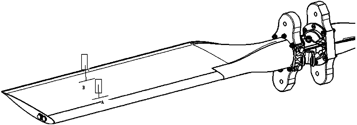
[0017] 1. There are errors in the installation of the laser displacement sensor, and it is difficult to ensure that the axis of the sensor is perpendicular to the measured surface of the blade;
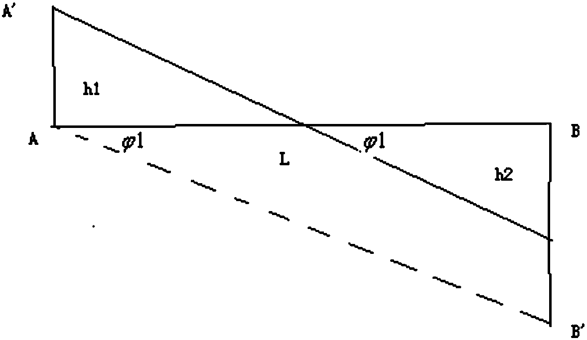
[0018] 2. There is a measurement error in the laser displacement sensor. Under the action of force, the tail rotor blade will be twisted and deformed, which will cause the position of the sensor measurement point to change. Since the measurement point for displacement deformation is not on the same plane as the surround
Method used
View moreImage
Smart ImageViewing Examples
Examples
 PUM
 Abstract
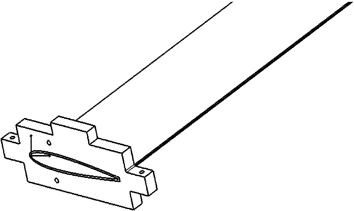
The invention discloses a test method for measuring the overall torsional rigidity of a blade, and belongs to the technical field of overall torsional rigidity tests on helicopter blades. The test method comprises the following steps: Step I, designing an aerofoil clamp according to an aerofoil profile of the blade; Step II, mounting the blade on a blade calibration table through the aerofoil clamp, and rotating the blade calibration table to enable the profile of a flexible beam of the blade to be located at a horizontal position; Step III, placing an angle gauge on a horizontal plane of theaerofoil clamp, and measuring an initial angle Psi1; Step IV, applying a load F at a rocker arm, and after the load F is stabilized, measuring an angle Psi2 of the aerofoil clamp; Step V, calculatinga torsion angle Psi of the overall torsional rigidity-tested profile of the blade under the action of the load F; Step VI, calculating the overall torsional rigidity of the blade by using the torsionangle Psi; Step VII, applying different levels of loads to the blade, calculating a corresponding torsional rigidity of the tested profile under each level of load, and linearly fitting the torsionalrigidities. The torsion angle measured by the test method disclosed by the invention is high in linearity and repetitiveness; test data are real and effective, and electromagnetic interference is avoided.
Description
technical field [0001] The invention belongs to the technical field of the overall torsional stiffness test of the helicopter blade, and in particular relates to a test method for measuring the overall torsional stiffness of the blade. Background technique [0002] In practice, we often need to measure the overall torsional stiffness of helicopter blades. The formula for calculating the overall torsional stiffness is: [0003] Gz=T / ψ=PL / ψ (1) [0004] In the formula: P——force couple value; [0005] L - the distance between two loads; [0006] ψ——the torsion angle of the specified section (unit rad). [0007] It can be seen from formula (1) that both P and L are constant values, and only ψ affects the torsional stiffness of the blade. Therefore, the study of ψ is very important to improve the accuracy of the torsional stiffness of the helicopter blade. [0008] Usually we use the following methods to test out ψ (such as figure 1 shown): [0009] 1. Rotate the blade cal...
Claims
Login to View More Application Information
Patent Timeline
 IPC IPC(8): G01M5/00
CPCG01M5/0016G01M5/005
Inventor 虞路长王崇唐江光杨丛青冯拯桥
Owner CHINA HELICOPTER RES & DEV INST
Features
- R&D
- Intellectual Property
- Life Sciences
- Materials
- Tech Scout
- Unparalleled Data Quality
- Higher Quality Content
- 60% Fewer Hallucinations
Learn More Browse by: Latest US Patents, China's latest patents, Technical Efficacy Thesaurus, Application Domain, Technology Topic, Popular Technical Reports.
© 2025 PatSnap. All rights reserved.Legal|Privacy policy|Modern Slavery Act Transparency Statement|Sitemap|About US| Contact US: help@patsnap.com


