Novel power supply facility

A facility and a new type of technology, applied in circuits, electrical components, coupling devices, etc., can solve problems such as unstable locking methods, accidental power outages, electric shocks, etc., to improve power supply stability, reduce accidental power outages, and simple device structure Effect

Inactive Publication Date: 2018-07-03
中山市新发装饰工程有限公司
View PDF5 Cites 19 Cited by
  • Summary
  • Abstract
  • Description
  • Claims
  • Application Information

AI Technical Summary

Problems solved by technology

[0002] Electrical equipment such as some household appliances and production equipment need to be powered on during operation, and electrical equipment is completed through the use of plug connectors and power sockets when they are powered on. Power sockets are designed according to their structure and purpose. The difference can be divided into many kinds, and most of the power sockets are installed in the wall. When in use, you only need to insert the plug connector into the socket in the power socket. The traditional power socket In the seat, the elastic conductive sheet protrudes out of the socket, and this elastic conductive sheet is also easily contacted by the metal sheet or rod. Therefore, when a person who lacks safety awareness inserts the metal sheet or rod into the socket It is easy to cause electric shock accidents, and it is easy to cause casualties; and the traditional plug connector and socket socket use the friction between the two to realize the locking of the inserted state, but this locking method is extremely unstable, and the plug connector is generally They are all protruding from the socket, the plug connector is easy to be touched or kicked, and it is easy to cause accidental power failure, and the power supply line is often easy to trip people. When people trip over the power supply line, it is easy to drive the plug connector loose. It is also easy to cause power failure of electrical equipment. Therefore, there are great disadvantages in traditional power sockets and plug connectors.

Method used


Image

  • Novel power supply facility
  • Novel power supply facility
  • Novel power supply facility

Examples


Embodiment Construction

[0027] All features disclosed in this specification, or steps in all methods or processes disclosed, may be combined in any manner, except for mutually exclusive features and / or steps.

[0028] Any feature disclosed in this specification (including any appended claims, abstract and drawings), unless expressly stated otherwise, may be replaced by alternative features which are equivalent or serve a similar purpose. That is, unless expressly stated otherwise, each feature is one example only of a series of equivalent or similar features.

[0029] Combine below Figure 1-8 The present invention will be described in detail.

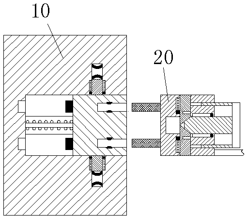
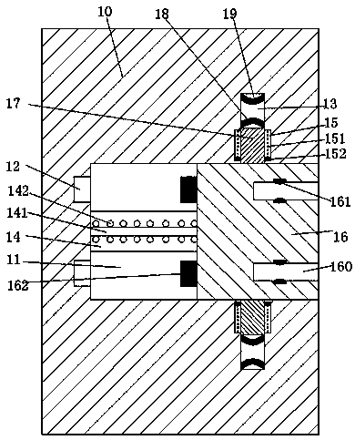
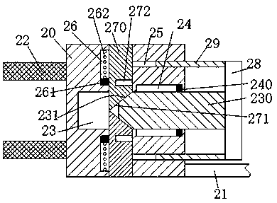
[0030] refer to Figure 1-8 , a new type of power supply facility according to an embodiment of the present invention, including a socket socket 10 fixedly installed in the wall and a plug connector 20 connected to an electrical device through a wire 21, the socket socket 10 is provided with an opening facing Right sliding cavity 11, sliding block 16 is sl...


PUM


Abstract

The invention discloses a novel power supply facility. The novel power supply facility comprises a plug socket fixedly mounted in a wall and a plug head connected with a power consumption apparatus via an electric wire, wherein the plug socket is provided with a sliding chamber which opens to the right, a sliding block is mounted in the sliding chamber in a sliding way, plugging grooves which opento the right are vertically symmetrically arranged in the sliding block, first elastic electric conduction sheets are mounted in the plugging grooves, a power supply block is fixedly arranged on a left end face of the sliding block, a power supply groove matched with the power supply block is arranged in a left end wall of the sliding chamber, telescoping grooves that extend up and down are symmetrically arranged in upper and lower end walls of the sliding chamber, and sliding arms are mounted in the telescoping grooves in a sliding manner; second elastic electric conduction sheets are fixedly mounted on end faces, positioned away from the sliding chamber, of the sliding arms; third elastic electric conduction sheets opposite to the second elastic electric conduction sheets are mounted inthe telescoping grooves, electric conduction arms matched with the plugging grooves are symmetrically arranged on an upper part and a lower part of a left end of the plug head, a lengthwise groove ofwhich an upper end and a lower end are communicated with each other is arranged in the plug head, and a horizontal groove which opens to the left and runs through the lengthwise groove is arranged inthe plug head.

Description

technical field [0001] The invention relates to the field of power supply for electrical equipment, in particular to a new type of power supply facility. Background technique [0002] Electrical equipment such as some household appliances and production equipment need to be powered on during operation, and electrical equipment is completed through the use of plug connectors and power sockets when they are powered on. Power sockets are designed according to their structure and purpose. The difference can be divided into many kinds, and most of the power sockets are installed in the wall. When in use, you only need to insert the plug connector into the socket in the power socket. The traditional power socket In the seat, the elastic conductive sheet protrudes out of the socket, and this elastic conductive sheet is also easily contacted by the metal sheet or rod. Therefore, when a person who lacks safety awareness inserts the metal sheet or rod into the socket It is easy to ca...

Claims


Application Information

Patent Timeline
Patent Type & Authority Applications(China)
IPC IPC(8): H01R13/70H01R13/639H01R13/502
CPCH01R13/701H01R13/502H01R13/639
Inventor 虞海杰
Owner 中山市新发装饰工程有限公司
Why Eureka
Try Eureka