Fumigation device for grain storage

A technology for fumigation devices and grains, which is applied to devices for capturing or killing insects, fumigators, measuring devices, etc. It can solve the problems of long dosing time and uneven distribution of phosphine concentration, so as to improve life expectancy and increase contact area , Improve the effect of fumigation efficiency

Inactive Publication Date: 2018-07-10
郑州龙威电气安装有限公司
View PDF0 Cites 10 Cited by
  • Summary
  • Abstract
  • Description
  • Claims
  • Application Information

AI Technical Summary

Problems solved by technology

[0004] In view of this, this application provides a fumigation device for grain storage, which solves the problems of long dosing tim

Method used


Image

  • Fumigation device for grain storage

Examples


Embodiment 1

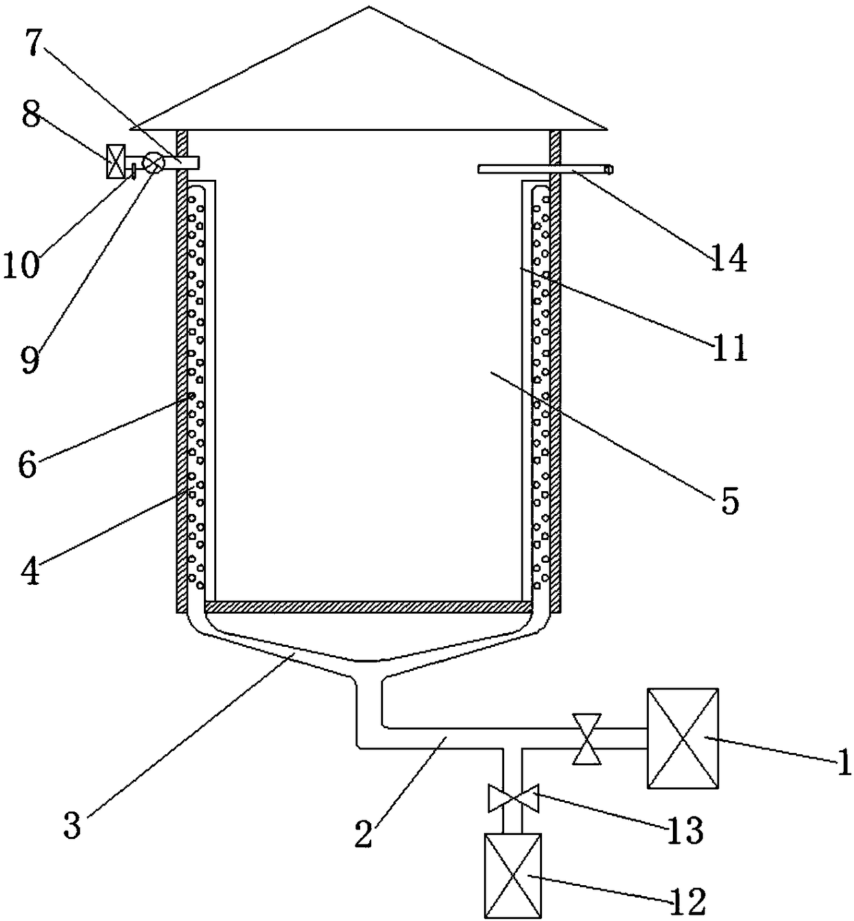
[0018] Such as figure 1 The shown fumigation device for grain storage includes a chemical gas box 1 located outside the granary 5 and a fumigation mechanism connected to the chemical gas box 1. The fumigation mechanism includes a main pipe 2 connected to the chemical gas box 1, and A plurality of branch pipes 3 communicated with the main pipe 2 and a fumigation pipe 4 communicated with each branch pipe 3, the fumigation pipe 4 is vertically fixed on the inner wall of the granary 5, the ends of the fumigation pipe 4 are closed, and there are A plurality of fumigation holes 6 are arranged, and an exhaust device communicating with the outside of the granary 5 is also provided on the silo wall at the top of the granary 5 .

[0019] In the granary 5 fumigation device described above, a plurality of fumigation pipes 4 fixed on the inner wall of the granary 5 are provided. Since the fumigation pipe 4 is provided with a plurality of fumigation holes 6, during the grain fumigation proc...

Embodiment 2

[0021] Based on Example 1, such as figure 1 As shown, there are multiple fumigation pipes 4 and they are evenly distributed on the inner wall of the granary 5 . A plurality of fumigation pipes 4 are evenly distributed on the inner wall of the granary 5, which further improves the efficiency of gas diffusion and the uniformity of fumigation.

Embodiment 3

[0023] Based on Example 1, such as figure 1 As shown, the exhaust device includes an exhaust pipe 7 communicated with the interior of the granary 5 and a cleaning device 8 connected to the exhaust pipe 7, and the exhaust pipe 7 is provided with an induced draft fan 9 and a first gas Density sensor 10. By arranging an exhaust device, and installing a gas purifier 8 in the exhaust device, the phosphine gas after the fumigation can be quickly discharged, so that the gas inside the granary 5 can reach a safe range, and the discharged phosphine gas can be purified at the same time discharge, to avoid the harm of highly toxic gas to the human body and the environment, and at the same time, the first gas concentration sensor 10 monitors the discharged gas in real time to meet the safe discharge index and solve the danger caused by the natural discharge of phosphine gas after the existing grain fumigation higher degree of problems.


PUM


Abstract

The invention provides a fumigation device for grain storage. The fumigation device comprises a chemical gas box positioned outside a granary, and a fumigation mechanism connected with the chemical gas box, wherein the fumigation mechanism comprises a main pipe connected with the chemical gas box, a plurality of branch pipes communicated with the main pipe, and a fumigation pipe communicated witheach branch pipe; the fumigation pipes are vertically fixed on the inner wall of the granary; the tail end of the fumigation pipes are closed, and the pipe walls of the fumigation pipes are evenly provided with a plurality of fumigation holes; the wall of the upper part of the granary is also provided with an exhaust device communicated with the exterior of the granary. The fumigation device for grain storage solves the problems of long chemical dosing time and uneven hydrogen phosphide concentration distribution in the existing grain fumigation process, and increases the fumigation efficiency.

Description

technical field [0001] The invention relates to the technical field of grain storage equipment, in particular to a fumigation device for grain storage. Background technique [0002] In the process of grain storage, due to the influence of various factors, stored grain pests often occur, and the annual losses due to grain mildew and insect pests account for a large proportion. If these stored pests are not effectively controlled and killed, it will not only cause A large loss of stored grain will also seriously affect the quality of stored grain, which is very harmful. Therefore, in the process of grain storage, it is necessary to effectively control and kill stored grain pests. [0003] At present, the main means of preventing and controlling insect pests in stored grains is to use chemical fumigation to fumigate and kill insects. Chemical fumigation is a technology that uses chemical fumigants to kill stored grain pests and germs in closed grain storage warehouses. Exterm...

Claims


Application Information

Patent Timeline
IPC IPC(8): A01M17/00A01M13/00G01N33/00
CPCA01M17/008A01M13/00G01N33/0036
Inventor 王波
Owner 郑州龙威电气安装有限公司
Why Eureka
Try Eureka