Method for producing a solid component, and a solid component

A technology of solid components and components, applied in the direction of tools, manufacturing tools, bearing components for lathes, etc., can solve problems such as high manufacturing costs

Active Publication Date: 2018-07-17
SCHAEFFLER TECH AG & CO KG
View PDF9 Cites 0 Cited by
  • Summary
  • Abstract
  • Description
  • Claims
  • Application Information

AI Technical Summary

Problems solved by technology

In addition to the high material requirements for the solid cage, the separate machining in partic

Method used


Image

  • Method for producing a solid component, and a solid component
  • Method for producing a solid component, and a solid component
  • Method for producing a solid component, and a solid component

Examples


Embodiment Construction

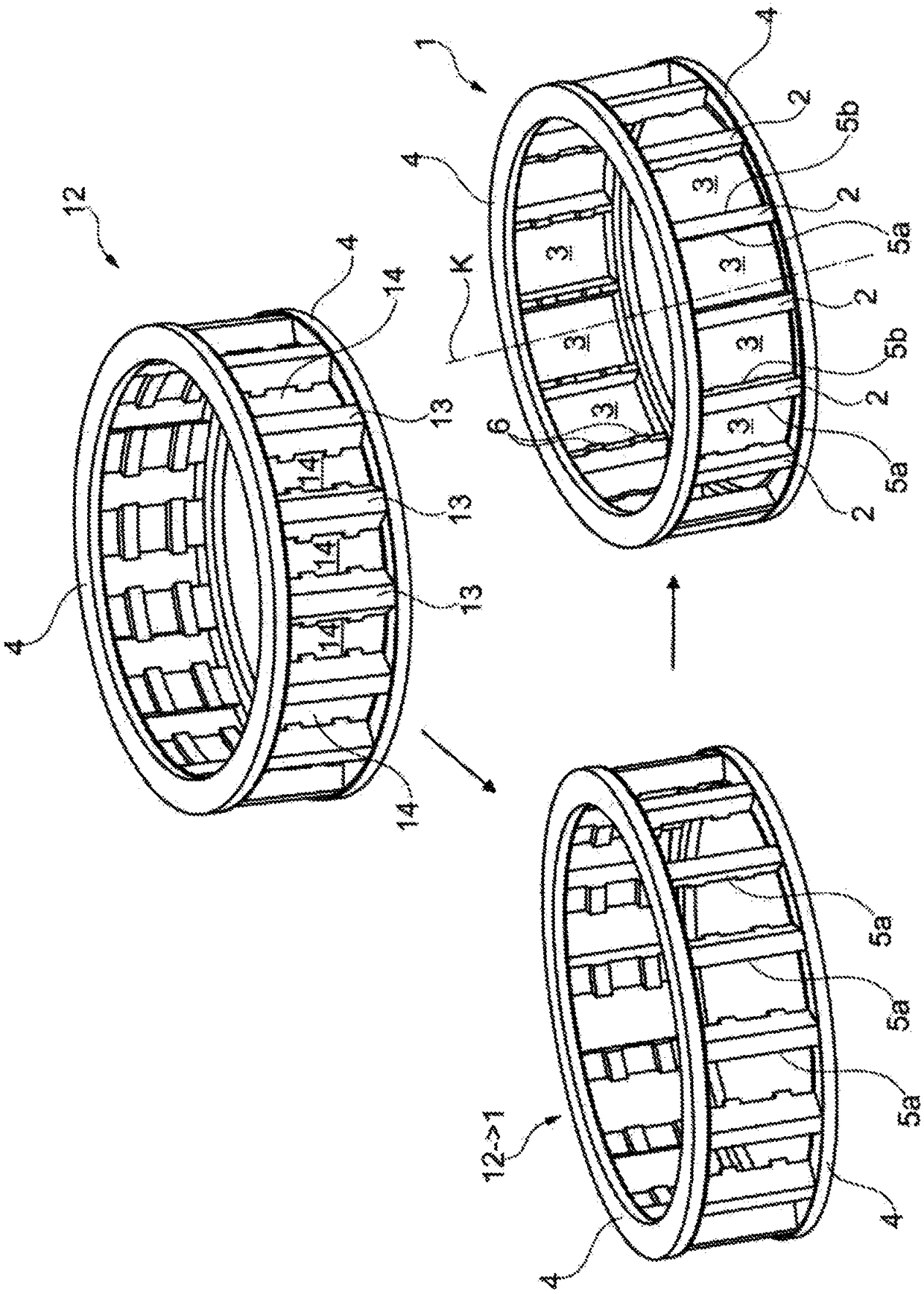
[0044] figure 1 shown for manufacture as in the figure 1 A schematic overview of the method of a solid cage 1 as a solid component is shown at the bottom right. The solid cage 1 is designed for insertion into a rolling bearing and has a plurality of webs 2 as intermediate regions, which are arranged regularly distributed in the circumferential direction about the axis of rotation K of the cage. Between the webs 2 there are respectively pockets 3 for accommodating rolling bodies, which are rollers in this example. Side rings 4 are arranged on the axial end side, wherein the webs 2 and / or the pockets 3 extend between the side rings 4 . The solid cage 1 is formed in one piece.

[0045] Each web 2 has a first web side 5a as the first pocket side and a second web side 5b as the second pocket side. exist figure 1 In the embodiment shown in , the first tab side is oriented clockwise and the second tab side is oriented counterclockwise. For reasons of clarity, only two webs 2 ar...


PUM

PropertyMeasurementUnit
Diameteraaaaaaaaaa

Abstract

Cages in rolling bearings are used to guide and space apart rolling bodies. The cages are often annular and have windows in which the rolling bodies are arranged. Along with plastic cages and sheet metal cages, solid cages are known which are machined from a solid semifinished product using separating methods. The invention relates to a method for producing a solid component. The production is carried out over two cycloidal machining steps. The solid cage (1) defines a cage rotational axis (K) and has a plurality of webs (2) which form pockets (3) for receiving rolling bodies. Each of the webs(2) has a first and a second web side (5a, b) for contacting the rolling body in the circumferential direction about the cage rotational axis (K). The method has the following steps: producing a cageblank (12), said cage blank (12) having a plurality of blank webs (13) which form blank pockets (14); producing the first web side (5a) using a tool blade (9), said tool blade (9) being guided relative to the cage blank (12) along a first cycloidal path in a first cycloidal machining step, wherein the first web sides (5a) are cut by the tool blade (9) and/or a cutting angle of the tool blade (9)is positive; and producing the second web side (5b) using a tool blade or the tool blade (9), said tool blade (9) being guided relative to the cage blank (12) along a second cycloidal path in a secondcycloidal machining step, wherein the second web sides (5b) are cut by the tool blade (9) and/or a cutting angle of the tool blade (9) is positive.

Description

technical field [0001] The invention relates to a method for producing a solid component having the features of claim 1 and to a solid component which is produced by means of this method. Background technique [0002] Cages in rolling bearings serve the purpose of: guiding the rolling elements and spacing them apart from one another. The cage is generally designed to be annular and has windows in which the rolling bodies are arranged. In addition to plastic cages and sheet metal cages, so-called solid cages are known which are produced from a solid semi-finished product by means of a separation method. In addition to the high material requirements for the solid cage, the separate machining in particular entails high manufacturing costs, since the windows are usually milled out one after the other. [0003] Another solution for producing a solid cage is proposed in reference DE 40 34 516 C2, which perhaps forms the closest prior art. In this reference, a method is describe...

Claims


Application Information

Patent Timeline
IPC IPC(8): F16C33/46F16C33/49B23Q27/00
CPCB23B5/36B23B27/005B23P15/003B23Q27/00F16C33/4629F16C33/497
Inventor 伯恩哈德·桑德斯托比亚斯·内特
Owner SCHAEFFLER TECH AG & CO KG
Why Eureka
Try Eureka