Food can airtightness detection apparatus

A technology for testing equipment and food cans, which can be used in the use of liquid/vacuum for liquid tightness measurement, and by measuring the acceleration and deceleration rates of fluids, which can solve problems such as pollution, deterioration, and lower product qualification rates

Active Publication Date: 2018-07-20
浙江金正检测有限公司
7 Cites 11 Cited by

AI-Extracted Technical Summary

Problems solved by technology

The airtightness of canned food determines the quality and qualification rate of canned food. Therefore, before canning, it is necessary to test the airtightness of food cans for canned food suc...

Method used

In addition, in this process, owing to form the first seal between the end face sealing gasket and the upper end face of food can, form the second seal between sealing cylinder and the inner surface of food can, can guarantee like this During the pressure keeping process o...

Abstract

The invention discloses a food can airtightness detection apparatus, in particular, a food can airtightness detection apparatus capable of quickly detecting the airtightness of food cans for canning food. The food can airtightness detection apparatus comprises a rack, a food can positioning seat arranged on the rack, and a airtightness detecting mechanism, wherein the airtightness detecting mechanism comprises a booster pump, a horizontal pressing plate located above the food can positioning seat, vertical guide sleeves which are arranged on the rack and are located above the horizontal pressing plate, vertical guide rods which are disposed on the horizontal pressing plate and are matched with the vertical guide sleeves, a floating support plate which lifts and descends along the verticalguide rods, a lifting cylinder which is arranged on the rack and is used for lifting and descending the floating support plate, an end surface sealing gasket which is disposed on the lower surface ofthe horizontal pressing plate, a sealing cylinder which is disposed on the lower surface of the end surface sealing gasket, a vertical pressurizing tube which is disposed at the upper end opening of the horizontal pressing plate, and a connection tube which is connected with the booster pump and the upper end opening of the vertical pressurizing tube.

Application Domain

Measurement of fluid loss/gain rate

Technology Topic

EngineeringBooster pump +4

Image

  • Food can airtightness detection apparatus
  • Food can airtightness detection apparatus
  • Food can airtightness detection apparatus

Examples

  • Experimental program(1)

Example Embodiment

[0022] The present invention will be further described in detail below in conjunction with the drawings and specific embodiments:
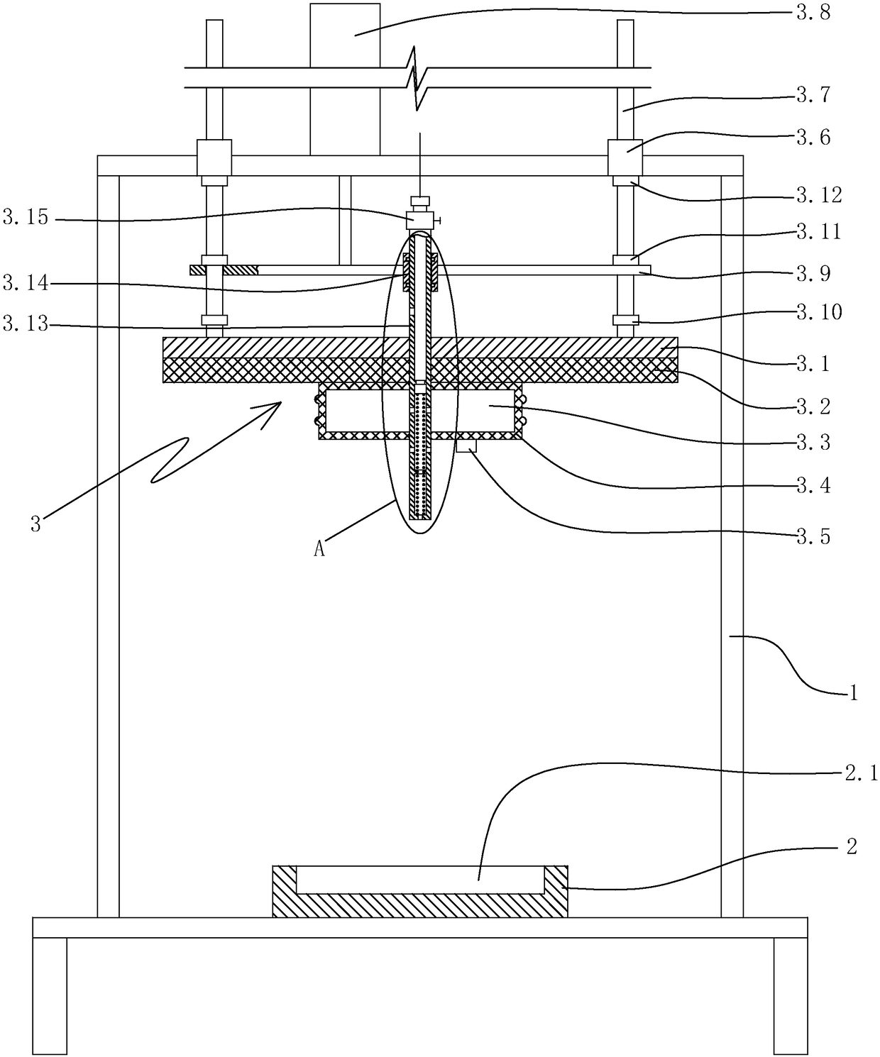
[0023] Such as figure 1 As shown, a food tank air tightness detection equipment includes a frame 1, a food tank positioning seat 2 arranged on the frame, and an air tightness detection mechanism 3.
[0024] The upper surface of the food can positioning seat is provided with a food can positioning groove 2.1 for positioning the food can, and the bottom surface of the food can positioning groove is a horizontal plane. The positioning groove for the food can in this embodiment is a round groove.
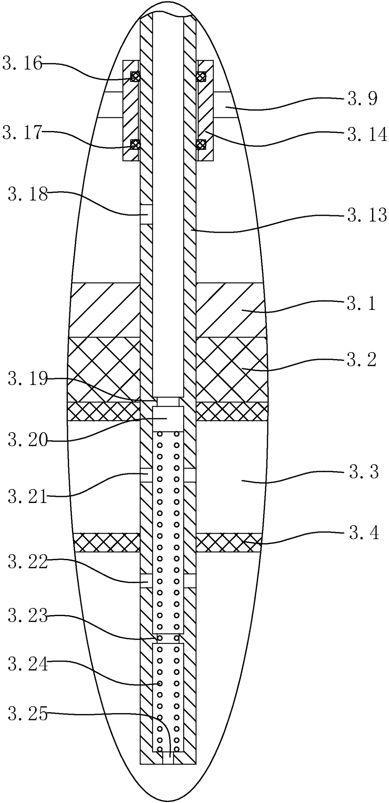
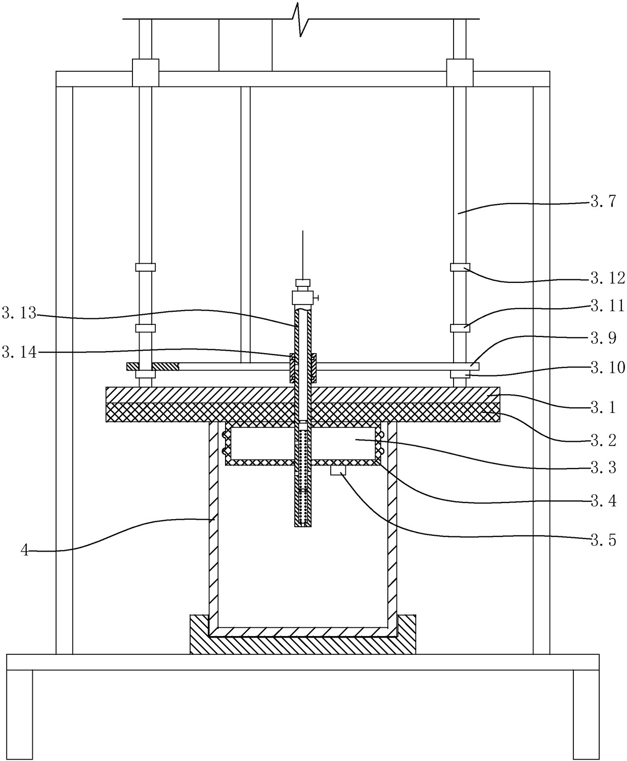
[0025] Such as figure 1 , figure 2 As shown, the air tightness detection mechanism includes a booster pump, a horizontal pressure plate 3.1 located above the food tank positioning seat, a vertical guide sleeve 3.6 arranged on the rack and above the horizontal pressure plate, and a horizontal pressure plate arranged on the horizontal pressure plate and connected to the vertical The vertical guide rod 3.7 matched with the guide sleeve, the first limit block 3.10, the second limit block 3.11 and the third limit block 3.12 arranged on the outer surface of the vertical guide rod from bottom to top, along the vertical guide The floating support plate 3.9 for lifting the rod, the lifting cylinder 3.8 for lifting the floating support plate arranged on the frame, the end face sealing gasket 3.2 arranged on the lower surface of the horizontal pressure plate, the end face sealing gasket 3.2 arranged on the lower surface of the end face sealing gasket The sealed cylinder 3.4 of the closed inflatable inner cavity 3.3, the air pressure detection sensor 3.5 arranged on the lower end surface of the sealed cylinder, the vertical booster pipe 3.13 with the upper end opened on the horizontal pressure plate, and the booster pump connected to the vertical A connecting pipe with an opening at the upper end of the booster pipe, a floating sliding sleeve 3.14 slidingly sleeved on the vertical boosting pipe, and an upper sealing ring 3.16 and a lower sealing ring 3.17 arranged on the inner side of the floating sliding sleeve. The gravity of the horizontal pressure plate is greater than the friction between the floating sliding sleeve and the vertical pressurizing pipe.
[0026] The end face gasket is a rubber gasket. In this embodiment, the thickness of the end face sealing gasket is greater than 5 mm.
[0027] The sealing cylinder is a rubber sealing cylinder. The sealing cylinder is a cylinder, and the axis of the sealing cylinder is vertically arranged. The sealing cylinder is located above the positioning groove of the food can. The axis of the sealing cylinder is coaxial with the axis of the positioning groove of the food can.
[0028] A number of annular sealing protrusions distributed sequentially from bottom to top are arranged on the outer surface of the sealing cylinder.
[0029] An on-off valve 3.15 is also provided between the connecting pipe and the upper opening of the vertical boosting pipe. In this embodiment, the connecting pipe is a connecting hose.
[0030] The lower end of the vertical guide rod is connected with the horizontal pressing plate.
[0031] The third limiting block is located below the vertical guide sleeve. The floating support plate is provided with a vertical guide through hole matched with the vertical guide rod, and the vertical guide rod passes through the corresponding vertical guide through hole. The floating support plate is located between the first limiting block and the second limiting block. The floating support plate is connected with the floating sliding sleeve.
[0032] The upper end of the vertical booster pipe is located above the horizontal pressure plate. The lower end of the vertical pressurizing pipe passes through the horizontal pressure plate, the end face sealing gasket and the sealing cylinder from top to bottom, and is located below the sealing cylinder. The outer surface of the vertical booster tube is provided with a first vent 3.18, a second vent 3.21, and a third vent 3.22 that communicate with the inner cavity of the vertical booster pipe. The first vent is located above the horizontal pressure plate. The second vent hole is located in the inflation inner cavity, and the second vent hole communicates the inflation inner cavity and the inner cavity of the vertical pressurizing tube. The third vent hole is located below the sealing cylinder. The lower end of the vertical pressurizing pipe is closed, and the lower end of the vertical pressurizing pipe is provided with an end face through hole 3.25.
[0033] An annular upper limit block 3.19 and an annular lower limit block 3.23 are provided on the inner surface of the vertical booster pipe. A floating piston 3.20 is provided in the vertical pressurizing pipe and located between the annular upper limit block and the annular lower limit block. A piston return spring 3.24 is provided in the vertical booster pipe and below the floating piston. The annular upper limit block is located between the first vent hole and the second vent hole, and the second vent hole and the third vent hole are located between the annular upper limit block and the annular lower limit block.
[0034] Such as figure 2 As shown, when the floating piston abuts on the annular upper limit block, the second vent hole and the third vent hole are located below the floating piston.
[0035] When the floating piston abuts on the annular lower limit block, the second vent hole and the third vent hole are located above the floating piston.
[0036] Such as figure 1 As shown, when the floating support plate abuts on the second limit block: the first vent is located below the floating sliding sleeve.
[0037] When the floating support plate abuts on the first limiting block: the first vent is located between the lower sealing ring and the upper sealing ring in the floating sliding sleeve.
[0038] The specific work of the food tank air tightness detection equipment of this embodiment is as follows:
[0039] The initial state of the food tank air tightness testing equipment, such as figure 1 As shown, at this time, the third limit block abuts on the lower end surface of the vertical guide sleeve, the floating piston abuts on the annular limit block, and the floating support plate abuts on the second limit block.
[0040] First, place the food can 4 in the food can positioning groove, with the upper port of the food can facing upward, and position the food can through the food can positioning groove, such as image 3 Shown.
[0041] Second, the lifting cylinder drives the floating support plate to move down. In this process:
[0042] The horizontal pressure plate, vertical guide rod, end face seal gasket, seal cylinder and vertical booster pipe will move down along the vertical guide sleeve under the action of their own weight, when the end face seal gasket abuts on the upper end of the food can , The horizontal pressure plate, the vertical guide rod, the end face sealing gasket, the sealing cylinder and the vertical booster pipe stop moving downwards. At this time, the sealing cylinder and the air pressure detection sensor are located in the upper port of the food tank (outside the sealing cylinder) Diameter smaller than the inner diameter of the food can);
[0043] Then, the lifting cylinder drives the floating support plate to move down. In this process: the floating sliding sleeve moves down along the vertical booster pipe. When the floating support plate is against the first limit block, the lifting cylinder drives the floating support plate. Continue to move down 1 mm, and then the lifting cylinder stops working. At this time: the first vent hole is located between the lower and upper seal rings in the floating sliding sleeve, the first vent hole is not connected to the outside world, and the end face sealing gasket is tight When pressed on the upper end surface of the food can, the first seal (end surface seal) is formed between the end face sealing gasket and the upper end face of the food can.
[0044] Third, open the on-off valve, the booster pump works, and pump air into the vertical booster pipe through the booster pump and the connecting pipe. In this process:
[0045] The floating piston in the vertical booster pipe first moves down. When the floating sliding sleeve is located between the second vent hole and the third vent hole, the gas pressed into the vertical booster pipe by the booster pump will enter the gas through the second vent hole The inner cavity makes the sealing cylinder expand and abut against the inner side of the food can, thereby forming a second seal (inner side seal) between the sealing cylinder and the inner side of the food can (the inner side near the upper end of the food can) ;
[0046] Then, the floating piston continues to move downwards until the floating piston abuts on the annular lower limit block. At this time, the gas pressed into the vertical boosting pipe by the booster pump will enter the food tank through the third vent; when the air pressure sensor detects When the air pressure in the food tank reaches the set value P1, the on-off valve is closed, the booster pump stops working, and the pressure in the food tank is maintained for 6 seconds, and then the air pressure P2 in the food tank is detected by the air pressure sensor;
[0047] Then, calculate the two air pressure differences △P, △P = P1- P2;
[0048] If △P is less than the set value, the air tightness of the canned food meets the requirements;
[0049] If △P is greater than the set value, it means that the air tightness of the canned food does not meet the requirements.
[0050] In addition, in this process, since the first seal is formed between the end face sealing gasket and the upper end of the food can, a second seal is formed between the sealing cylinder and the inner side of the food can, which can ensure the preservation of the food can. During the pressing process, the gas in the food can will not leak due to the poor sealing effect between the end face sealing gasket and the food can, which will cause △P to be greater than the set value and cause misjudgment, which effectively improves the food can The detection accuracy of air tightness.
[0051] Fourth, the lifting cylinder drives the floating support plate to move. In this process:
[0052] The floating support plate and the floating sliding sleeve will move up first (the horizontal pressure plate, the vertical guide rod, the end face seal gasket, the sealing cylinder and the vertical booster pipe remain basically unchanged), when the first vent hole is located on the floating sliding sleeve When below, the first vent is connected to the outside, so that the gas in the inflatable inner cavity is discharged through the second vent, the vertical pressurizing tube and the first vent, so that the sealing cylinder is contracted and separated from the food can; After the floating support plate abuts on the second limit block, the floating support plate drives the horizontal pressure plate, the vertical guide rod, the end face seal gasket, the sealing cylinder and the vertical booster pipe to move upward together; at the same time, the floating piston is in place. The piston moves up and resets under the action of the return spring;
[0053] Since the sealing cylinder shrinks and separates from the food tank, when the floating support plate abuts on the second limit block, the floating support plate drives the horizontal pressure plate, the vertical guide rod, the end seal gasket, the sealing cylinder and the vertical increase. When the pressure tube moves upward together, it will not drive the food can up together (the sealed cylinder shrinks and separates from the food can), and the sealed cylinder is separated from the food can smoothly, ensuring that the food can after the air tightness test can be smoothly tested. take out.
[0054] Fifth, take out the food cans that have completed the air tightness test.

PUM

no PUM

Description & Claims & Application Information

We can also present the details of the Description, Claims and Application information to help users get a comprehensive understanding of the technical details of the patent, such as background art, summary of invention, brief description of drawings, description of embodiments, and other original content. On the other hand, users can also determine the specific scope of protection of the technology through the list of claims; as well as understand the changes in the life cycle of the technology with the presentation of the patent timeline. Login to view more.
Why Eureka
Try Eureka