Impeller structure of mixed transportation pump

A mixed pump and impeller technology, applied to pumps, parts of pumping devices for elastic fluids, pump elements, etc., can solve the problems of increased hydraulic loss of stationary impellers, large vortices of stationary impellers, low efficiency of mixed pumps, etc. , to achieve the effects of reduced vortex and hydraulic loss, improved booster performance, and increased efficiency

Active Publication Date: 2018-08-14
XIHUA UNIV
View PDF6 Cites 0 Cited by
  • Summary
  • Abstract
  • Description
  • Claims
  • Application Information

AI Technical Summary

Problems solved by technology

[0002] The cross-section of the vane of the static impeller of the existing mixed pump is an airfoil, and the blade profile curves in one direction. Large vortices appear in the stationary impeller, resulting in increased hydraulic loss in the stationary impeller
Therefore, when this static impeller is used, the efficiency of the mixed pump is low
In addition, the flow path of the static impeller of the existing mixed pump is relatively short, and the boosting effect is not ideal. To achieve a large lift, more stages must be used

Method used


Image

  • Impeller structure of mixed transportation pump
  • Impeller structure of mixed transportation pump
  • Impeller structure of mixed transportation pump

Examples


Embodiment Construction

[0021] The present invention is specifically described below through the examples, the examples are only used to further illustrate the present invention, and cannot be interpreted as limiting the protection scope of the present invention, some non-essential improvements made by those skilled in the art according to the contents of the present invention And adjustments also belong to the protection scope of the present invention.

[0022] In conjunction with the accompanying drawings.

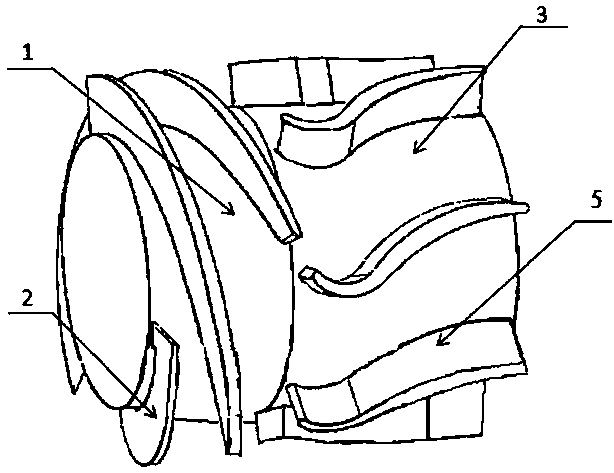
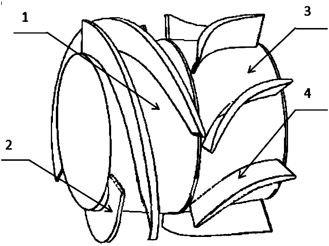
[0023] Such as figure 1 As shown, the impeller structure of the mixed transport pump includes the moving impeller 1 and its moving impeller blade 2 and the stationary impeller 3 and its stationary impeller blade 5. 2 have the same outlet direction, and the placement angle of the static impeller blade 5 outlet is 90 degrees.

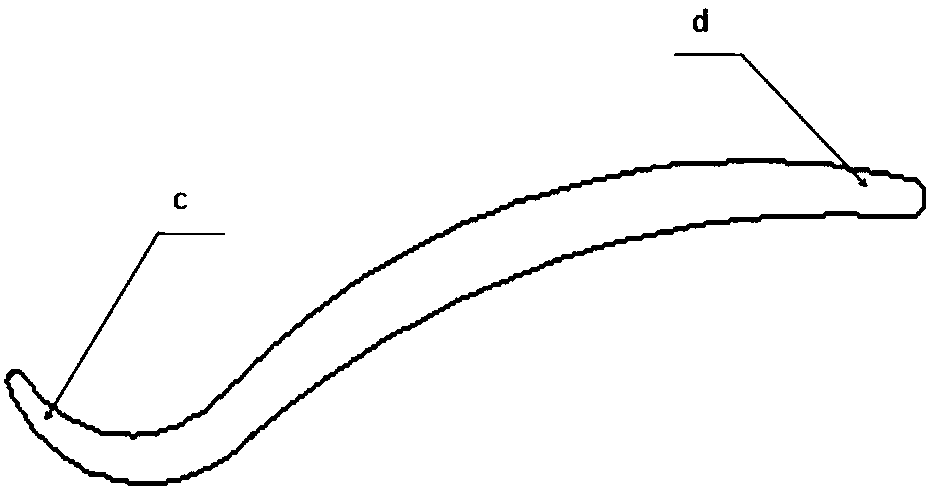
[0024] Such as figure 1 , figure 2 As shown, the bending direction of the inlet section c of the vane of the stationary impeller is opposite to that of the outlet sec...


PUM


Abstract

The invention discloses an impeller structure of a mixed transportation pump. The impeller structure comprises a movable impeller and movable impeller blades thereof, a static impeller and static impeller blades thereof; molded lines of the static impeller blades are S-shaped; inlet directions of the static impeller blades are the same with outlet directions of the movable impeller blades; outletplacing angles of the static impeller blades are 90 degrees; bending directions of inlet sections of the static impeller blades are opposite to bending directions of outlet sections; lengths of the inlet sections of the blades are 1 / 3 of the whole blade length; the molded lines are of smooth gentle transition structures; inlet and outlet thicknesses are smaller than thicknesses of the middle partsof the blades; the inlet positions of the static impeller blades are in front of the outlet positions of the static impeller blades; and seven blades are provided, and are uniformly arranged in the peripheral direction of the static impeller. The molded lines of the static impeller blades are S-shaped, and the inlet directions of the static impeller blades are the same with the outlet directionsof the movable impeller blades, so that the vortex and hydraulic loss in the static impeller of the mixed transportation pump are reduced, the supercharging performance of the static impeller is improved, and the efficiency of the mixed transportation pump is improved.

Description

technical field [0001] The invention belongs to the technical field of design and manufacture of delivery pumps, in particular to the design and manufacture of impellers of mixed delivery pumps. Background technique [0002] The cross-section of the vane of the static impeller of the existing mixed pump is an airfoil, and the blade profile curves in one direction. Large vortices appear in the stationary impeller, resulting in increased hydraulic loss in the stationary impeller. Therefore, when this static impeller is used, the efficiency of the mixed pump is low. In addition, the flow path of the stationary impeller of the existing mixed pump is short, and the boosting effect is not ideal. To achieve a large lift, more stages must be used. Contents of the invention [0003] According to the deficiencies of the prior art, the invention discloses an impeller structure of a mixed pump. The problem to be solved by the present invention is to provide a static impeller of a m...

Claims


Application Information

Patent Timeline
IPC IPC(8): F04D29/18
CPCF04D29/185
Inventor 史广泰王闪姚显彤罗琨王志文
Owner XIHUA UNIV
Why Eureka
Try Eureka