Supercharge pump device

A technology of pump device and main vane, applied in the field of conveying pump and booster pump, can solve the problems of pressure loss, enlarged flow passage, etc., and achieve the effect of reducing pressure loss, improving supercharging performance and improving supercharging effect.

Active Publication Date: 2021-09-28
JINGDEZHEN CERAMIC INSTITUTE
View PDF0 Cites 0 Cited by
  • Summary
  • Abstract
  • Description
  • Claims
  • Application Information

AI Technical Summary

Problems solved by technology

However, the existing centrifugal pump has the problem of a certain amount of pressure loss caused by the wall laminar flow upstream of the flared flow channel due to the enlarged flow channel of the flared flow channel.

Method used


Image

  • Supercharge pump device
  • Supercharge pump device
  • Supercharge pump device

Examples


Embodiment Construction

[0018] In order to make the purpose, technical solutions and advantages of the embodiments of the present invention clearer, the technical solutions in the embodiments of the present invention will be clearly and completely described below in conjunction with the drawings in the embodiments of the present invention. Obviously, the described embodiments It is a part of embodiments of the present invention, but not all embodiments. Based on the embodiments of the present invention, all other embodiments obtained by persons of ordinary skill in the art without creative efforts fall within the protection scope of the present invention.

[0019] The present invention will be described in further detail below in conjunction with the accompanying drawings.

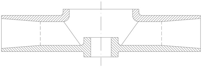
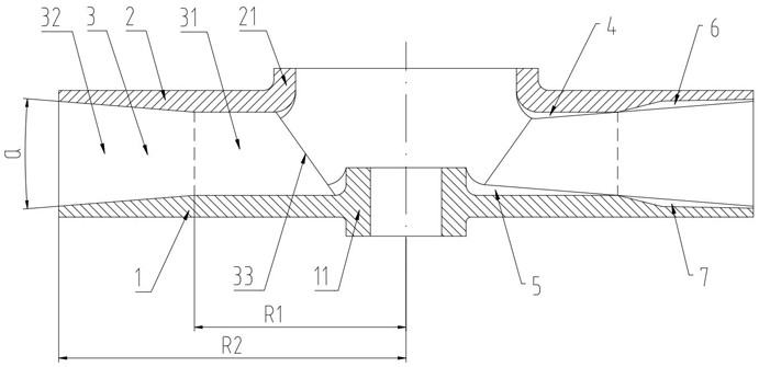
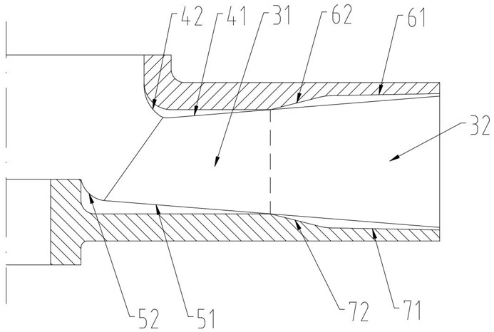
[0020] Such as Figure 2-3 As shown, a booster pump device includes a centrifugal impeller and a volute. The centrifugal impeller includes a bottom plate 1, a sleeve 11, a cover plate 2, an inlet ring 21, and main blades 3. A pl...


PUM


Abstract

The invention discloses a supercharge pump device. A centrifugal impeller of the supercharge pump device comprises a bottom plate (1), a cover plate (2) and main blades (3), the main blade comprises a first main blade portion (31) and a second main blade portion (32), a flaring flow channel is formed by the second flow channel width relative to the first flow channel width, and the flaring flow channel has a flaring angle a. The supercharge pump device is characterized in that in the circumferential direction, one or more first auxiliary blades (4) are arranged between every two adjacent main blades, one or more second auxiliary blades (5) are arranged between every two adjacent main blades, one side of each first auxiliary blade is connected to the inner side of the cover plate, and the other side of each first auxiliary blade is a free end; and one side of each second auxiliary blade is connected to the inner side of the bottom plate, the other side of each second auxiliary blade is a free end, and the outer diameter of the first auxiliary blade and the second auxiliary blade is smaller than or equal to that of the first main blade portion. Through the design of the first auxiliary blades and the second auxiliary blades, the wall-attached laminar flow in front of the flaring flow channel can be reduced, so that the pressure loss of the flaring flow channel is reduced, and the pressurization performance of the pump is improved.

Description

technical field [0001] The invention relates to the technical field of delivery pumps and booster pumps, in particular to a booster pump device. Background technique [0002] Such as figure 1 As shown, the existing centrifugal pump includes a centrifugal impeller and a volute. The centrifugal impeller includes a bottom plate, a sleeve, a cover plate, an inlet ring, and a main blade. A plurality of main blades are evenly distributed along the circumference and connected between the bottom plate and the cover plate. Between, the radial inner side of the bottom plate is provided with a sleeve, the radial inner side of the cover plate is provided with an inlet ring, the main blade includes a first main blade part, a second main blade part, and a front edge, and the first main blade part is defined between the bottom plate and the front edge. a first flow path width between the cover plates, the second main blade portion defines a second flow path width between the base plate an...

Claims


Application Information

Patent Timeline
IPC IPC(8): F04D29/24F04D29/00
CPCF04D29/242F04D29/007
Inventor 郁永彬余姗姗肖楠孙俊
Owner JINGDEZHEN CERAMIC INSTITUTE
Why Eureka
Try Eureka