
Subsection dedusting device for a vacuum cleaner

a vacuum cleaner and sub-section technology, applied in the direction of cleaning filter means, separation processes, filtration separation, etc., can solve the problems of bringing users trouble, affecting the performance and life of the vacuum cleaner, and the bulk of the cyclonic dedusting device is relatively large, so as to increase the whole bulk of the machine, increase the dedusting efficiency, and increase the effect of wind quantity

Active Publication Date: 2009-06-02
SUZHOU KINGCLEAN FLOORCARE
View PDF2 Cites 33 Cited by
  • Summary
  • Abstract
  • Description
  • Claims
  • Application Information

AI Technical Summary

Benefits of technology

"The present invention provides a subsection deducting device for a vacuum cleaner that includes an upper cyclone separator and several lower cyclone separators. The device has a wind outlet of the upper cyclone separator communicated with wind inlets of the lower cyclone separators, which increases wind quantity without increasing the overall size of the machine and keeps a relatively high dedusting efficiency. The lower cyclone separators are located below the upper cyclone separator and have a slower rotation speed, which prevents dust on the bottom of the dust cup from being raised again without causing secondary pollution. The device also includes a wind outlet cover and a wind exhaust tube to guide the air flow and improve the efficiency of the device."

Problems solved by technology

One traditional vacuum cleaner is arranged with a filter device for filtering suctioned dust-laden air, and leaving dust particles in a dust collecting device, so that the filter device should be cleaned or replaced after used for a period of time, otherwise, fine dust may clog filter holes of the filter device, which will increase resistance of the dedust motor, even burn the motor out, thereby not only bringing trouble for users, but also adversely affecting performance and life-span of the vacuum cleaner.
However, the cyclonic dedusting device has a relatively large bulk, especially a cyclonic dedusting device used for a large vacuum cleaner requiring a relatively large air flow has a larger bulk, which not only increases manufacturing cost thereof, but also brings much inconvenience for users.

Method used


Image

  • Subsection dedusting device for a vacuum cleaner
  • Subsection dedusting device for a vacuum cleaner
  • Subsection dedusting device for a vacuum cleaner

Examples


Embodiment Construction

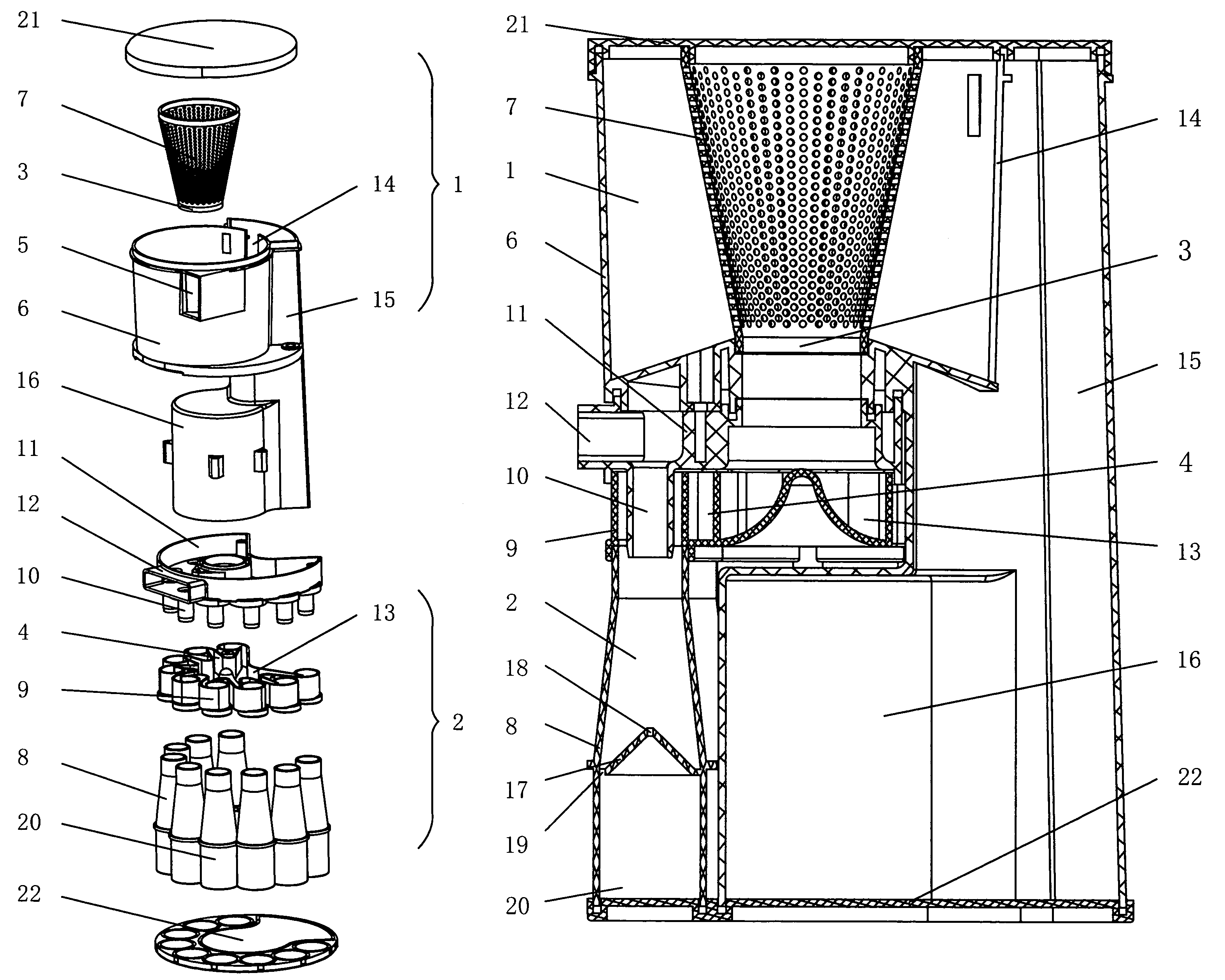
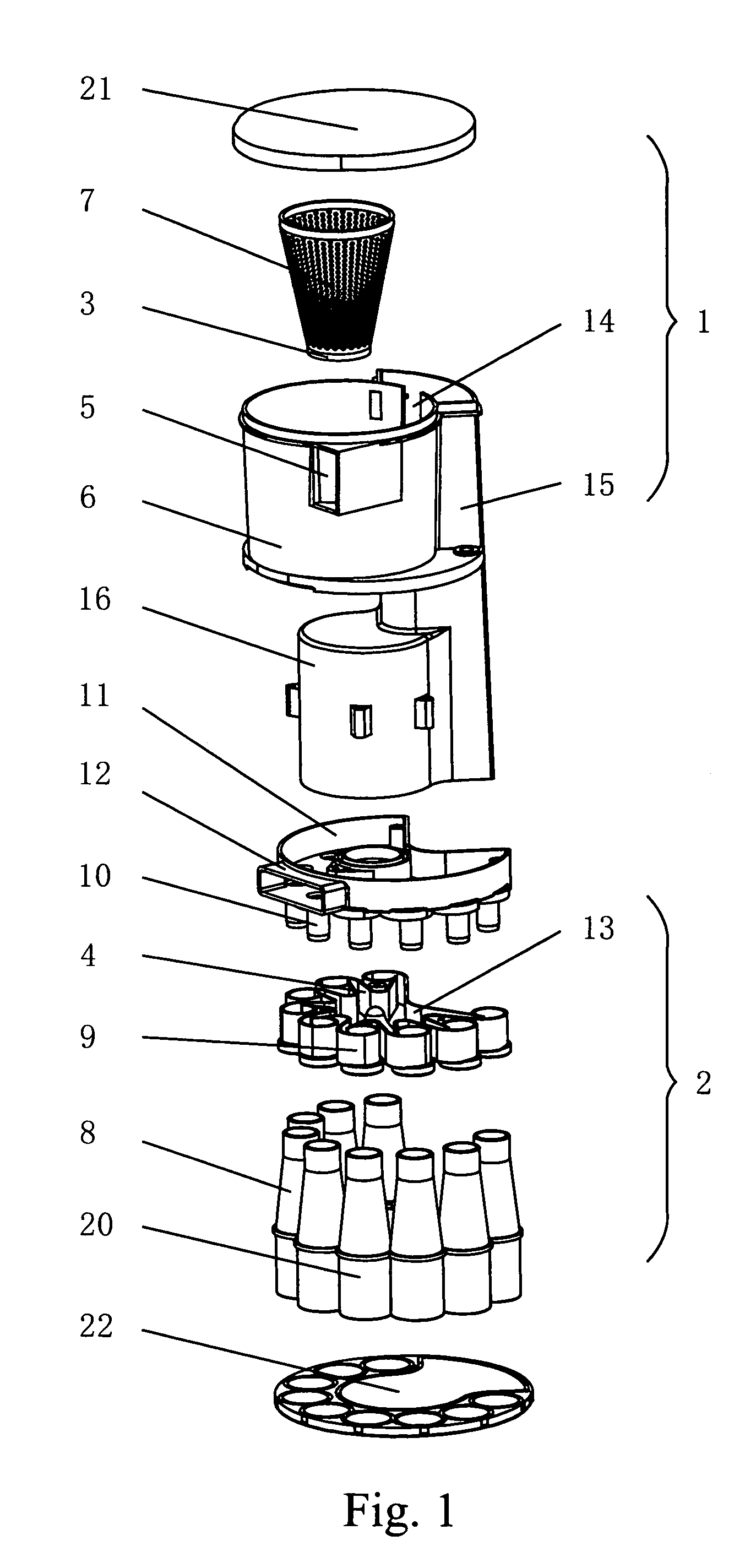
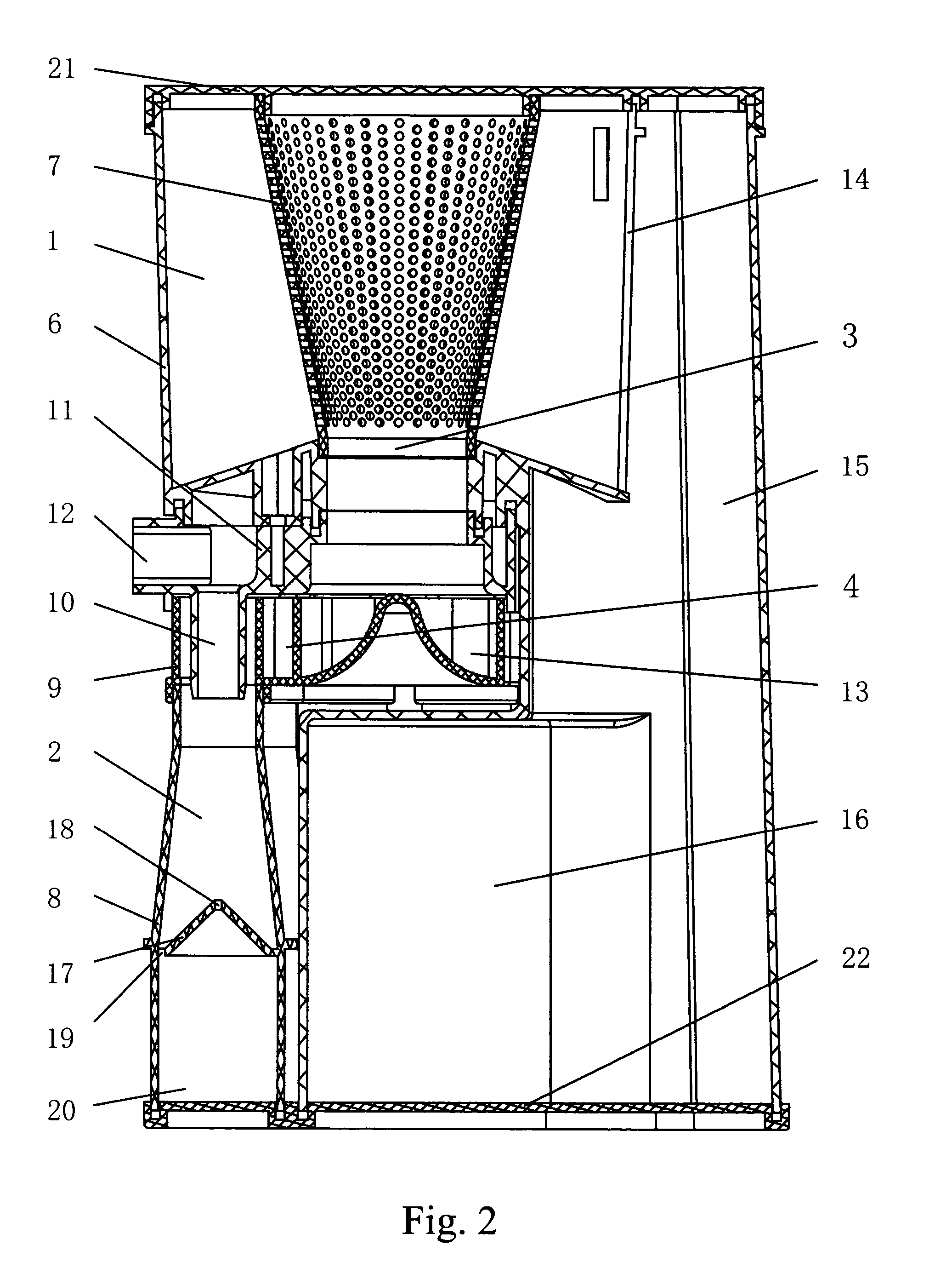
[0018]Embodiments: referring to FIGS. 1, 2, and 3, a subsection dedusting device for a vacuum cleaner, comprises an upper cyclone separator 1 and nine lower cyclone separators 2, and the lower cyclone separators 2 are located below the upper cyclone separator 1, the upper cyclone separator 1 includes a cylinder dust cup 6 having a cyclone wind inlet 5. A cylinder filter cover 7 with pores thereon is coaxially arranged in the cylinder dust cup 6, top end openings of the cylinder dust cup 6 and the cylinder filter cover 7 are sealed by a top cover 21, a bottom end opening of the cylinder filter cover 7 is used as a wind outlet 3 of the upper cyclone separator 1 and is located at a lower end of the cylinder dust cup 6. A dust collecting opening 14 is defined on a side portion of the cylinder dust cup 6, which is communicated with a dust collecting barrel 15, a circular dust collecting barrel 16 projects out of the lower portion of the dust collecting barrel 15 and is located below the ...


PUM

PropertyMeasurementUnit
resistanceaaaaaaaaaa
centrifugal forceaaaaaaaaaa
pressure lossaaaaaaaaaa

Abstract

This invention discloses a subsection dedusting device for a vacuum cleaner comprising an upper cyclone separator including a wind outlet and several lower cyclone separators located below said upper cyclone separator, wind inlets of said lower cyclone separators in fluid communication with said wind outlet of said upper cyclone separator, thereby increasing wind quantity while reducing the whole bulk of the machine, and keeping a relatively high dedusting efficiency, and besides the lower cyclone separator of the present invention adopts a pervasion construction, and air flow rotates in a decelerated and acentric state in the conical barrel, thereby the pressure loss of the air flow is little, and accordingly, obtain a good dust suction effect.

Description

FIELD OF INVENTION[0001]The present invention relates to a subsection dedusting device for a vacuum cleaner.BACKGROUND OF THE INVENTION[0002]One traditional vacuum cleaner is arranged with a filter device for filtering suctioned dust-laden air, and leaving dust particles in a dust collecting device, so that the filter device should be cleaned or replaced after used for a period of time, otherwise, fine dust may clog filter holes of the filter device, which will increase resistance of the dedust motor, even burn the motor out, thereby not only bringing trouble for users, but also adversely affecting performance and life-span of the vacuum cleaner.[0003]In recent years, a cyclonic dedusting device is widely used in vacuum cleaner instead of the filter device by manufacturers according to the principle of cyclone separation, which has obtained a relatively fine dedusting effect. The cyclonic dedusting device mounts a conical barrel with a large upper end and a relatively small lower en...

Claims


Application Information

Patent Timeline
Patent Type & Authority Patents(United States)
IPC IPC(8): B01D45/12
CPCA47L9/1625A47L9/1641Y10S55/03A47L9/16A47L9/1616A47L9/1658A47L9/1683B04C5/185B04C5/187B04C5/24B04C5/26
Inventor NI, ZUGEN
Owner SUZHOU KINGCLEAN FLOORCARE
Learn More