Soffit vent

a vent system and soffit technology, applied in ventilation systems, lighting and heating apparatus, heating types, etc., can solve the problems of not providing for the passage of insects or other elements into the building structure, and achieve the effect of maximizing the efficiency of a ventilation system or natural ventilation, and increasing airflow into the building structur

Inactive Publication Date: 2006-10-26
BUILDING MATERIALS INVESTMENT
View PDF14 Cites 32 Cited by
  • Summary
  • Abstract
  • Description
  • Claims
  • Application Information

AI Technical Summary

Benefits of technology

[0007] This invention provides an improved soffit vent that increases airflow into the building structure thus maximizing the efficiency of a ventilation system or natural ventilation. The soffit vent comprises a curved bottom panel with extending side walls adapted to be fixed to the soffit area of the building structure creating a front opening and channel for conveying air. The bottom panel can be contoured to direct and / or streamline the flow of air. The side walls can also be contoured to direct and / or streamline the flow of air.
[0010] The bottom panel of the vent preferably extends at its proximal or distal end to create an angle relative to the soffit area of the building structure of 1-180 degrees. The bottom panel may also curve of a given radius from the proximal or distal end to the opposite end. Alternatively the bottom may extend in a substantially planar design to the opposite end. This design provides for increased movement of air as the vent is positioned away from the eave overhang surface, thereby effectively increasing wind-aided air volume. The bottom panel and side walls can extend above the soffit area of the building structure. This embodiment provides for greater direction of airflow into the building space being vented.

Problems solved by technology

The openings preferable allow for the easy passage of air but do not provide for the passage of insects or other elements into the building structure.

Method used


Image

  • Soffit vent
  • Soffit vent
  • Soffit vent

Examples


Embodiment Construction

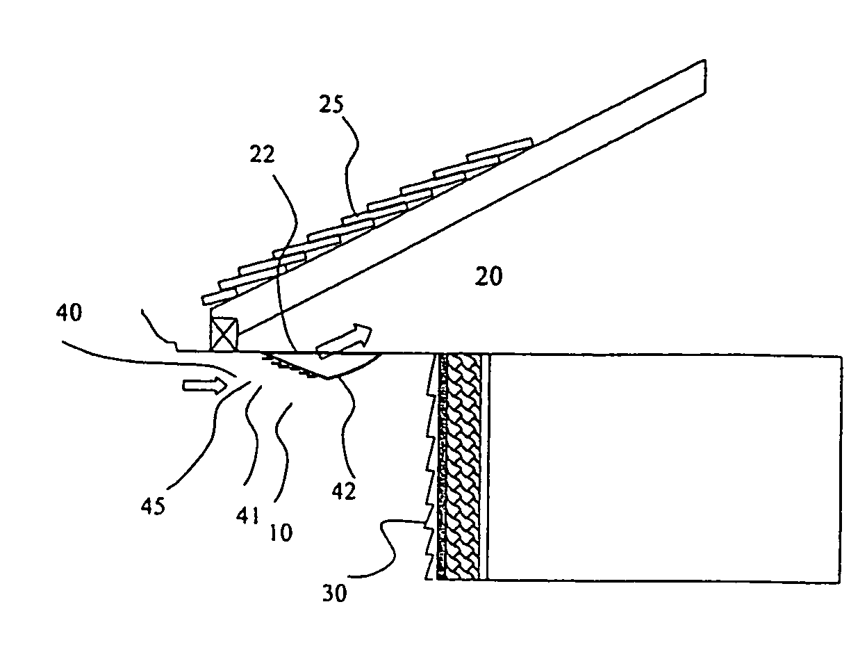
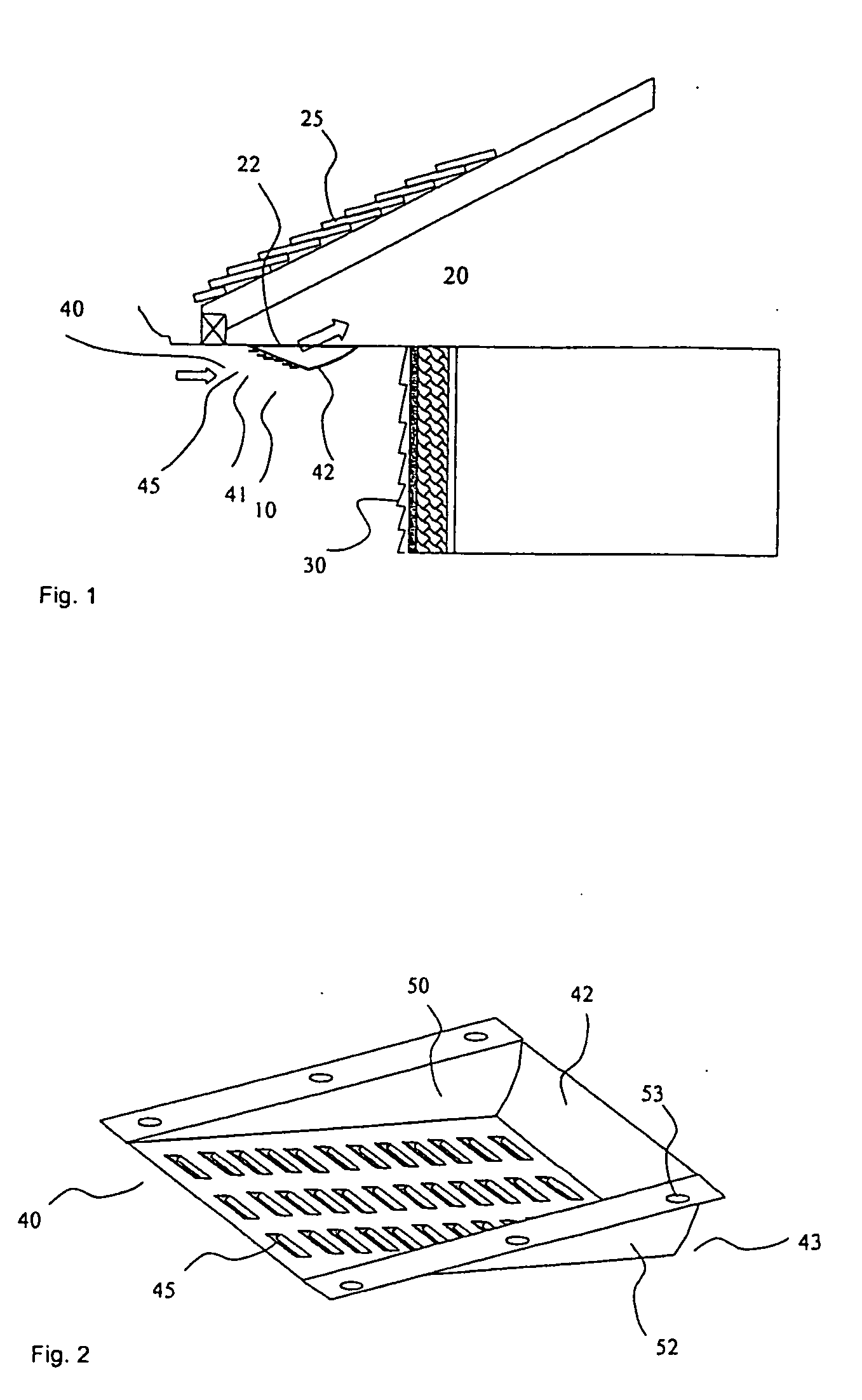
[0023] The present invention provides an improved soffit vent that maximizes the flow of air into a building structure through a vent in the structures soffit. In FIG. 1 the schematic shows a side view of vent 10 as installed on a building structure. The vent has front openings at its distal end 40 to allow for the passage of air from the surrounding environment. The air flows into the openings 41 in a curved bottom 42 and is directed up into the structure space 20 above the eave soffit opening or soffit area 22 by the curved bottom 42. It is preferred that the curved bottom 42 is louvered with slats 45 at the openings 41 however other designs include, but are not limited to, perforated screens, expanded metal, and slotted plates. The curve of the bottom 42 is of a given radius to aerodynamically convey intake air into the soffit area opening. The bottom 42 may or may not be inclined.

[0024] The slats can be fixed or movable, horizontal, vertical, or inclined and admit air while hel...


PUM


Abstract

A soffit vent comprising a unitary bottom panel with extending side walls, one or more interior walls extending from the bottom panel, a one or more open channels created by the side walls, interior walls and bottom panel and one or more closed channels adjacent to the open channels.

Description

FIELD OF THE INVENTION [0001] This invention relates generally to a soffit vent system that provides for venting of a building or other structure while preventing insects and environmental elements, such as water and snow, from entering the structure through the ventilator and can be made to fit a variety of pre-existing and newly constructed buildings. BACKGROUND OF THE INVENTION [0002] A soffit or eave is the exposed undersurfaces of any exterior overhanging section of a roof eave. A soffit vent is typically an air inlet source located at the downslope eave or in the soffit of a roof assembly. Soffit vents typically comprise perforated, louvered or baffled vent openings in the underside of the eaves of an overhanging roof or the fascia covering the ends of roof rafters when the roof has no soffit or has very narrow soffit. Soffit vents are commonly part of an attic ventilation system that may comprise roof vents, ridge vents, gable vents, power vents, roof louvers, turbines and th...

Claims


Application Information

Patent Timeline
Patent Type & Authority Applications(United States)
IPC IPC(8): F24F7/02
CPCF24F7/02E04D13/152
Inventor RAILKAR, SUDHIRZARATE, WALTERCHICH, ADEM
Owner BUILDING MATERIALS INVESTMENT
Why Eureka
Try Eureka