Floor type air conditioner indoor machine

A technology for floor-standing air conditioners and indoor units, which is applied in air-conditioning systems, heating methods, mechanical equipment, etc., can solve the problems of low utilization efficiency of heat exchangers, affecting the heat exchange capacity of heat exchangers, and lack of practical value, etc. The effect of heat exchange and heat exchange efficiency, simple and reasonable structure, and wide application range

Inactive Publication Date: 2011-01-26
GUANGDONG MIDEA ELECTRIC APPLIANCES CO LTD
View PDF3 Cites 32 Cited by
  • Summary
  • Abstract
  • Description
  • Claims
  • Application Information

AI Technical Summary

Problems solved by technology

The heat exchangers are all in the form of flat plates or V-shaped, and all of them need to enter the air from the back or the front of the cabinet, resulting in low utilization efficiency of the heat exchanger, and the air duct structure formed with the cross-flow wind wheel cannot be optimal. And due to the installation form of the cabinet machine, the air intake from the back is too low, or the cabinet machine cannot enter the air at all when it is installed against the wall, which greatly affects the heat exchange capacity of the heat exchanger and lacks practical value

Method used


Image

  • Floor type air conditioner indoor machine
  • Floor type air conditioner indoor machine
  • Floor type air conditioner indoor machine

Examples


no. 1 example

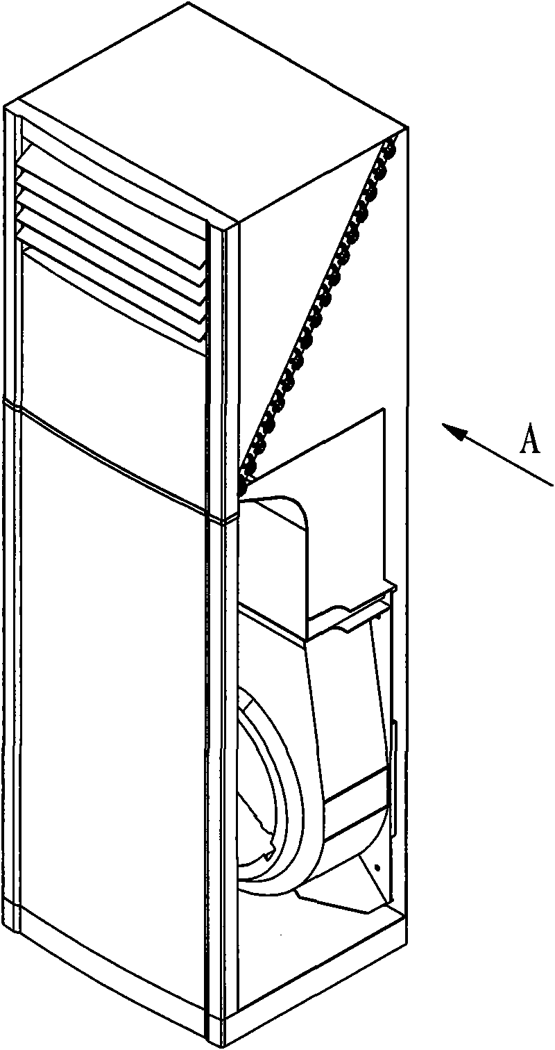
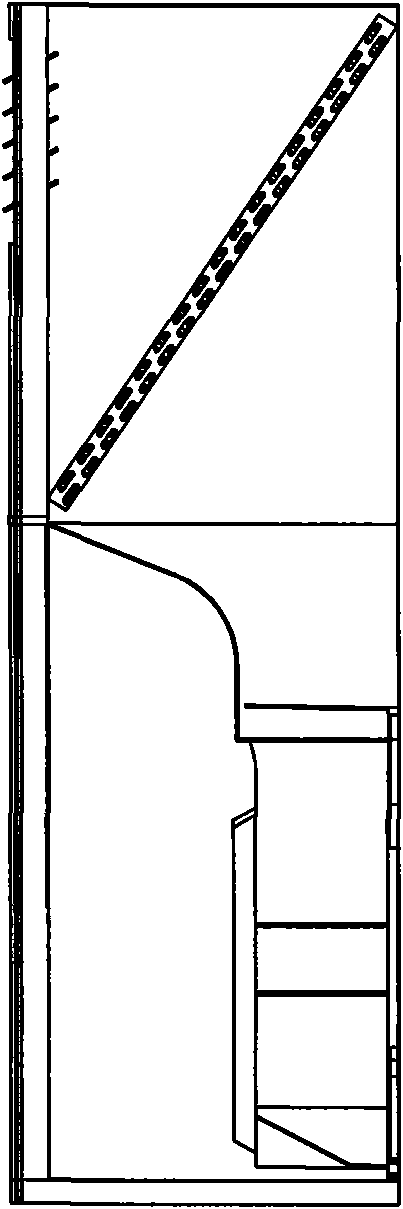
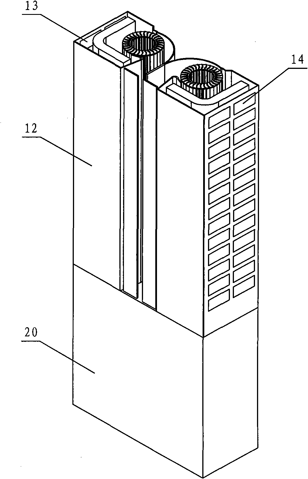
[0029] see Figure 3-Figure 4 with Figure 9-Figure 10 , this floor-standing air conditioner indoor unit includes an upper frame 12 arranged on the body 20, a heat exchanger, a cross-flow fan wheel and an air duct for accommodating the heat exchanger, a cross-flow wind wheel are arranged in the upper frame 12, and the upper frame 12 is provided with There are air inlets and air outlets communicating with the air duct, the cross-flow wind wheel includes a left cross-flow wind wheel 2 and a right cross-flow wind wheel 7 arranged in the horizontal direction, and the heat exchanger includes a left heat exchanger 3 and a right heat exchanger arranged in the horizontal direction The heat exchanger 6, the left heat exchanger 3 is arranged around the left cross-flow wind wheel 2, the right heat exchanger 6 is arranged around the right cross-flow wind wheel 7, and the left heat exchanger 3 and the right heat exchanger 6 are arc folded respectively. Curved, the air inlet includes a lef...

no. 2 example

[0043] see Figure 5-Figure 6 with Figure 9-Figure 10 , in this embodiment, the air outlets are the second air outlet 8 and the third air outlet 10, the second air outlet 8 is provided with the second air guide vane group 9, and the third air outlet 10 is provided with the third air guide Blade set 11. The air duct is the third air duct 33, the first partition 33.1 separates the left cross-flow wind wheel 2 and the right cross-flow wind wheel 7 in the third air duct 33, the upper part of the third air duct 33 is connected, and the third air duct The bottom of 33 is provided with second air outlet 8 and the 3rd air outlet 10 respectively, the left side of the 3rd air channel 33 communicates with the left air inlet 13, the right side of the 3rd air channel 33 communicates with the right air inlet 14; The air outlet 8 and the right air outlet 10 are located on both sides of the front of the upper frame 12; the third air duct 33 is respectively provided with curved surfaces cor...

no. 3 example

[0049] see Figure 7-Figure 10 , in this embodiment, the air outlets are the second air outlet 8 and the third air outlet 10, the second air outlet 8 is provided with the second air guide vane group 9, and the third air outlet 10 is provided with the third air guide Blade set 11. The air passage is the fourth air passage 34 and the fifth air passage 35, the left heat exchanger 3 and the left cross-flow wind wheel 2 are arranged in the fourth air passage 34, and the right heat exchanger 6 and the right cross-flow wind wheel 7 are arranged in the fifth air passage. In the air duct 35, one end of the fourth air duct 34 communicates with the left air inlet 13, the other end of the fourth air duct 34 communicates with the second air outlet 8, and one end of the fifth air duct 35 communicates with the right air inlet 14. The other end of the five air ducts 35 communicates with the third air outlet 10; the left air outlet 8 and the right air outlet 10 are located on both sides of th...


PUM


Abstract

The invention relates to a floor type air conditioner indoor machine which comprises an upper frame arranged on a machine body. Heat exchangers, cross flow wind wheels and an air duct for accommodating the heat exchangers and the cross flow wind wheels are arranged in the upper frame, and air inlets and an air outlet communicated with the air duct are arranged on the upper frame. The cross flow wind wheels comprise a left cross flow wind wheel and a right cross flow wind wheel arranged along the horizontal direction. The heat exchangers comprise a left heat exchanger and a right heat exchanger arranged along the horizontal direction, the left heat exchanger is arranged around the left cross flow wind wheel, the right heat exchanger is arranged around the right cross flow wind wheel, and the left heat exchanger and the right heat exchanger are respectively in arc bending shape. The air inlets comprise a left air inlet and a right air inlet, and the left air inlet and the right air inlet are respectively arranged on the left side and the right side of the upper frame, wherein the air outlet is the first air outlet, and a first wind guide vane group is arranged in the first air outlet. The invention has the characteristics of simple and reasonable structure, small complete machine size, low manufacturing cost, high energy efficiency ratio and wide application range and is flexible for operation.

Description

technical field [0001] The invention relates to a floor-standing air conditioner indoor unit. Background technique [0002] Traditional floor-standing air-conditioning indoor units, such as attached figure 1 - attached figure 2 As shown, it adopts a single centrifugal wind wheel structure. In order to increase the heat exchange area, it is often realized by increasing the thickness of the fuselage, increasing the width or height of the fuselage. When the size of the fuselage is increased, the aesthetics of the product will be reduced, and the wind speed of different parts of the heat exchanger will vary greatly, which will not give full play to the heat exchange performance of the heat exchanger. When the air volume is increased by increasing the speed of the wind rotor, problems such as increased noise are caused. [0003] Simultaneously other similar cabinet indoor units that use double cross-flow wind wheels, disclosed a kind of double cross-flow split body floor type...

Claims


Application Information

Patent Timeline
Patent Type & Authority Applications(China)
IPC IPC(8): F24F1/00F24F13/30F04D25/16
Inventor 张智伍光辉周拨黎文斗曾昭顺岳宝贾庆贤赵夫峰蔡序杰
Owner GUANGDONG MIDEA ELECTRIC APPLIANCES CO LTD
Why Eureka
Try Eureka