Centrifugal fan and aeration device with indoor air purifying function

A technology of centrifugal fan and fresh air device, which is applied to the components of pumping device for elastic fluid, pump device, mechanical equipment, etc., can solve the problem of increasing the load of indoor temperature adjustment equipment, shortening the service life of temperature adjustment equipment, Improve indoor air quality and other issues to achieve the effect of increasing work efficiency and air supply, shortening length and reducing energy consumption

Inactive Publication Date: 2008-01-09
JINYIXIN ELECTRONICS PLANT SHENZHEN LONGGANG DISTRICT
View PDF0 Cites 33 Cited by
  • Summary
  • Abstract
  • Description
  • Claims
  • Application Information

AI Technical Summary

Problems solved by technology

Existing ventilator majority only considers to provide fresh air indoors, discharge indoor dirty air simultaneously, but there are following problems at least in this type of ventilator: 1, existing ventilator inhales fresh air in a large amount, although can reach exchanging However, when the indoor and outdoor temperature difference is large, it will inevitably increase the load on the indoor temperature adjustment equipment, shorten the service life of the temperature adjustment equipment, and increase energy consumption.
2. Existing ventilation devices are usually equipped with an input port for outdoor air to the room, and at the same time, an air outlet for indoor air to be discharged to the outside. After the circulation circle related to the wind force diameter is installed, it is discharged to the outside, resulting in the existence of indoor ventilation dead angle
3. Existing ventilation devices usually cannot improve indoor air quality and reduce the requirement for outdoor fresh air by purifying indoor air, nor can they reduce the workload of air-conditioning equipment to achieve the purpose of healthy and energy-saving indoors

Method used


Image

  • Centrifugal fan and aeration device with indoor air purifying function
  • Centrifugal fan and aeration device with indoor air purifying function
  • Centrifugal fan and aeration device with indoor air purifying function

Examples


Embodiment Construction

[0034] The following examples are further explanations and illustrations of the present invention, and do not constitute any limitation to the present invention.

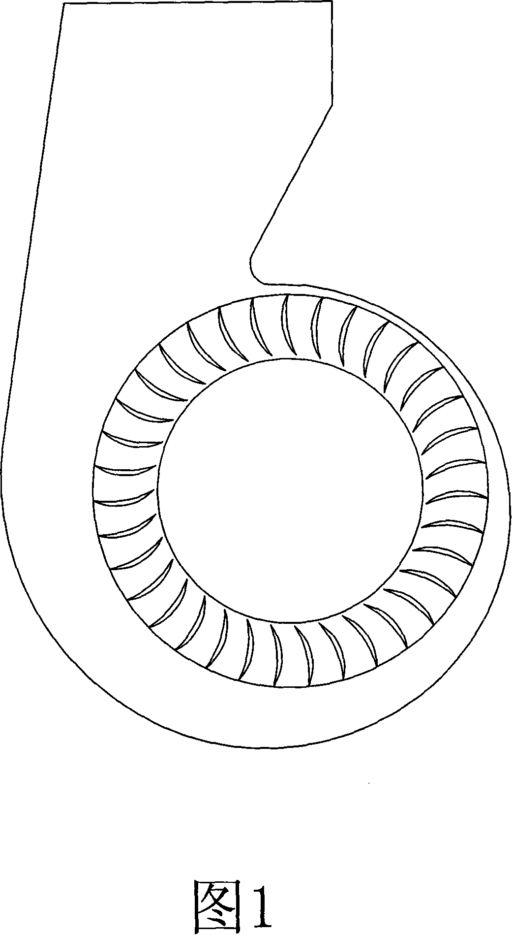
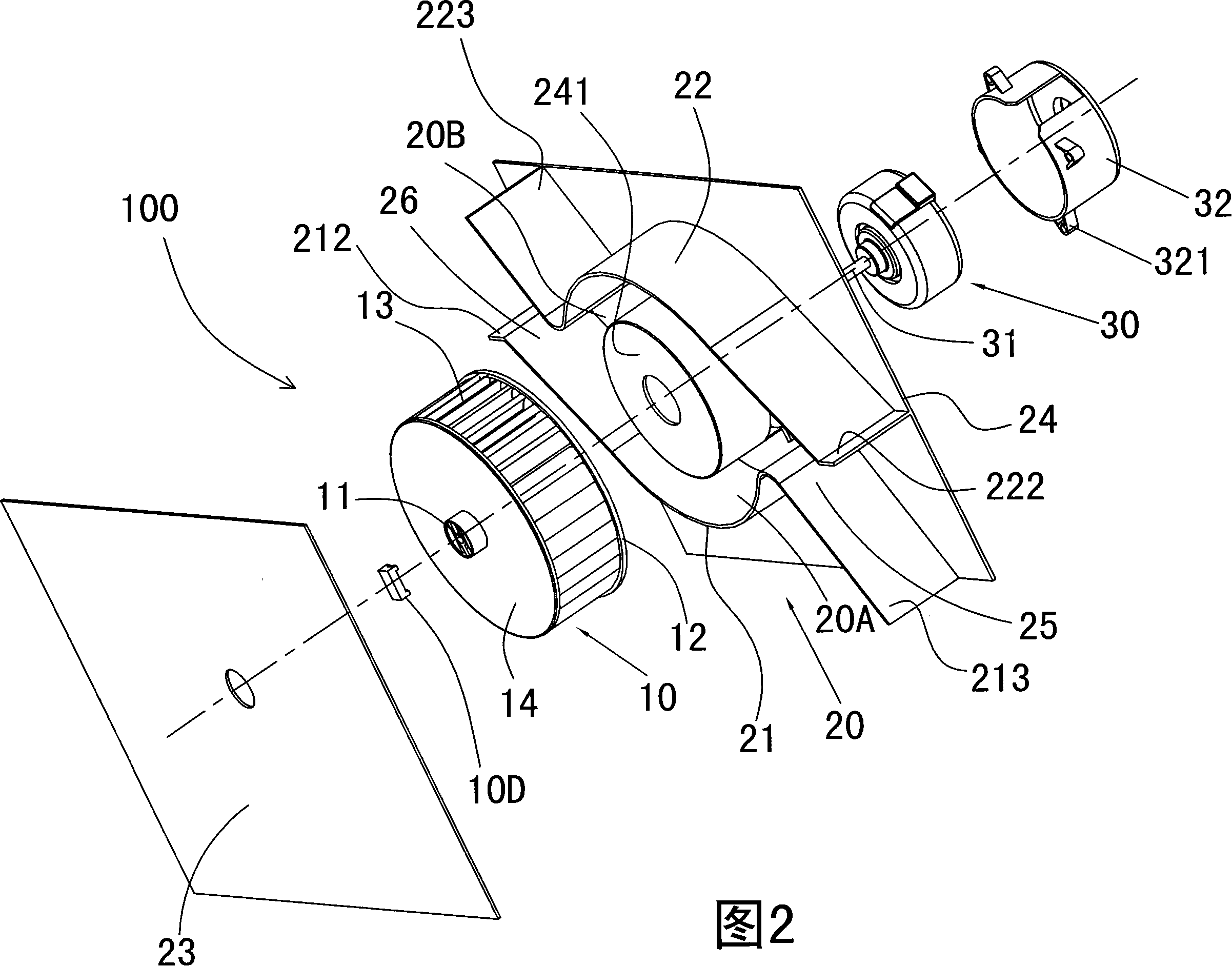
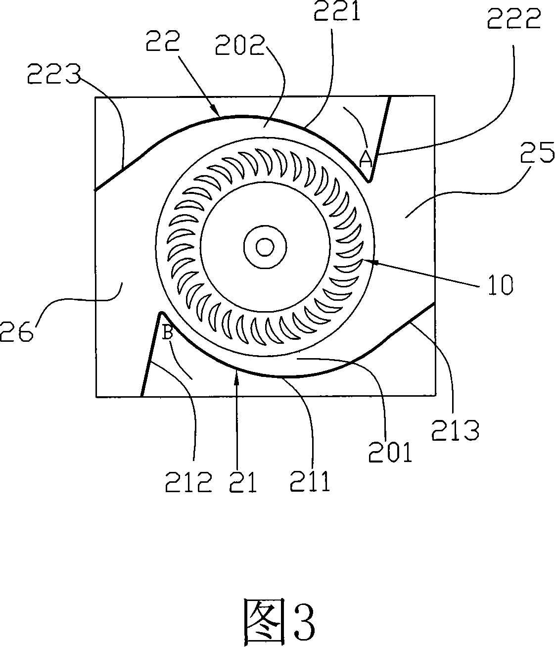
[0035] Referring to Fig. 2 and Fig. 3, the centrifugal fan 100 of the present invention includes a wind wheel 10, an air duct 20 and a motor 30. In Fig. 2, the wind wheel 10 is a hollow wheel-shaped body made of engineering plastics. The ring-shaped wheel frame 12 on the rear side and a plurality of crescent-shaped blades 13 arranged at intervals along the circumference of the wheel frame and its front end wall 14 are formed, and a connecting shaft seat 11 is arranged in the center of the end wall. The air duct 20 is the key point of the present invention, it is the channel that guides the airflow blown out by the wind wheel to flow in a predetermined direction, as shown in Figure 2 and Figure 3, the air duct 20 is composed of two air duct plates 21, 22 and the cavity formed between the front side plate 23, the rear...


PUM


Abstract

This invention is centrifuge type fan and fresh air device with indoor air purifying function. The centrifuge type fan includes wind wheel; wind channel on external part of wind wheel; engine driving the wind wheel. The said wind channel is the cavity formed by two wind channel boards, front side board, back side board and external surface of wind wheel. The front and back side boards connect to both sides of two wing channel boards. Both ends of wind channel have an air current outlet opening. Thus, they form double wind channels with double outlet openings. The absorbed air current is discharged to two directions at same time through two wind channels and two air outlet openings. The fresh air device includes machine case; centrifuge type fan group combined by two centrifuge type fans; air filtrating element; front board for control and display. This invention increases working efficiency. It also reduces noise and energy loss.

Description

【Technical field】 [0001] The present invention relates to a centrifugal fan, in particular to a centrifugal fan which is matched with two independent air passages and two air outlets by a centrifugal wind wheel to form a simultaneous reverse air outlet, and a centrifugal fan made of this centrifugal fan with Fresh air device with indoor air purification function. 【Background technique】 [0002] People widely use air conditioners, ventilators, fans and other air-conditioning and air-driven devices or equipment in daily life, and these devices tend to be more and more miniaturized. Among various forms of air supply devices, centrifugal fans are widely used due to their compact structure, small size, large air pressure, and long air supply distance. [0003] The structure of the known centrifugal fan is shown in Figure 1. It is provided with a long volute on the outside of the wind wheel. This kind of long volute is used to accelerate and guide the airflow, so as to increase ...

Claims


Application Information

Patent Timeline
Patent Type & Authority Applications(China)
IPC IPC(8): F04D29/42F04D29/30F04D25/16F04D29/70F04D27/00F04D29/00
Inventor 李壮藩
Owner JINYIXIN ELECTRONICS PLANT SHENZHEN LONGGANG DISTRICT
Why Eureka
Try Eureka