Cyclone dust collecting apparatus for vacuum cleaner

a vacuum cleaner and dust collection technology, applied in the field of vacuum cleaners, can solve the problems of large pressure loss, inability of conventional cyclone dust collection apparatus to separate fine dust from dust-laden air, etc., and achieve the effect of small pressure loss and higher fine dust collection efficiency

Active Publication Date: 2010-03-16
SAMSUNG GWANGJU ELECTRONICS CO LTD
View PDF23 Cites 33 Cited by
  • Summary
  • Abstract
  • Description
  • Claims
  • Application Information

AI Technical Summary

Benefits of technology

[0012]The present disclosure has been developed in order to overcome the above drawbacks and other problems associated with the conventional arrangement. An aspect of the present disclosure is to provide a cyclone dust collecting apparatus for a vacuum cleaner having a smaller pressure loss and a higher fine dust collecting efficiency than the conventional cyclone dust collecting apparatus.
[0023]The cyclone dust collecting apparatus further comprises a dust cap disposed at a bottom end of the second cyclone, the dust cap preventing fine dust collected in the second dust collecting chamber from flowing back.

Problems solved by technology

However, the conventional cyclone dust collecting apparatus cannot separate fine dust well from the dust-laden air because there is a little difference between weights of the fine dust and the air.
However, the conventional multi-cyclone dust collecting apparatus has a problem that a great pressure loss occurs when the dust-laden air is drawn-in from an inner cyclone to an outer cyclone.

Method used


Image

  • Cyclone dust collecting apparatus for vacuum cleaner
  • Cyclone dust collecting apparatus for vacuum cleaner
  • Cyclone dust collecting apparatus for vacuum cleaner

Examples


first embodiment

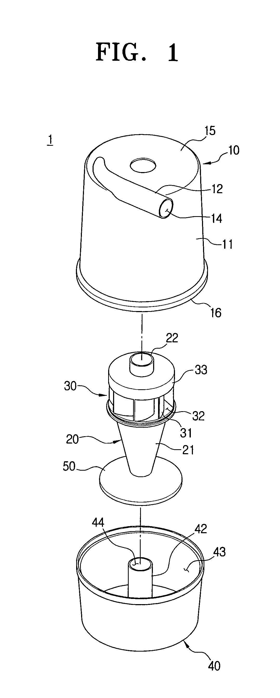
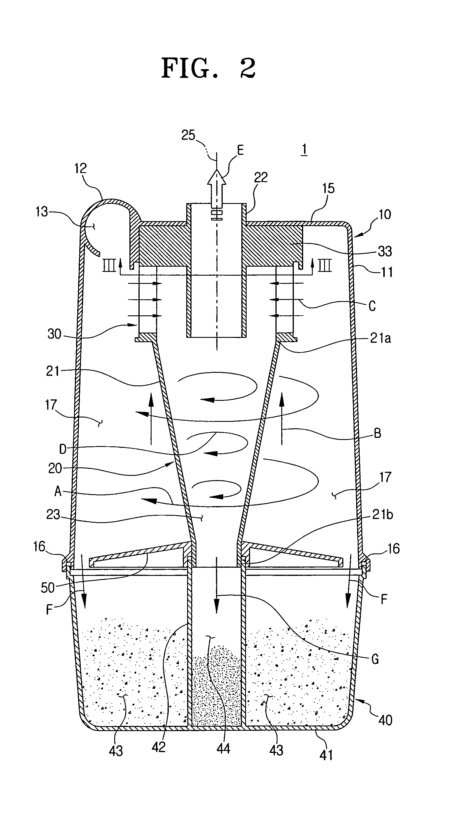
[0052]Referring to FIGS. 1 and 2, a cyclone dust collecting apparatus 1 for a vacuum cleaner according to the present disclosure includes a first cyclone 10, a second cyclone 20, and a dust collecting receptacle 40.

[0053]The first cyclone 10 draws-in outside air containing dust, dirt, and so on (hereinafter, referred to as dust-laden air), and forces the dust-laden air to downwardly whirl inside the first cyclone 10 so that dust, dirt and so on (hereinafter, referred to as dust) is separated from the dust-laden air by centrifugal force. Then, the first cyclone 10 discharges air having dust partially removed (hereinafter, referred to as semi-clean air) to the second cyclone 20.

[0054]The first cyclone 10 has a first cyclone body 11 and an air suction pipe 12. The first cyclone body 11 is formed in a substantially hollow cylindrical shape with a top end closed by a top wall 15 and an opened bottom end. At an upper side of the first cyclone body 11 is formed an air suction hole 13 throu...

second embodiment

[0069]Hereinafter, a cyclone dust collecting apparatus 2 for a vacuum cleaner according to the present disclosure is explained with reference to FIGS. 5 to 8D.

[0070]Referring to FIGS. 5 and 6, a cyclone dust collecting apparatus 2 for a vacuum cleaner according to the second embodiment of the present disclosure includes a first cyclone 10, a second cyclone 20′, and a dust collecting receptacle 40.

[0071]The cyclone dust collecting apparatus 2 according to the second embodiment has the same first cyclone 10 and dust collecting receptacle 40 as those of the cyclone dust collecting apparatus 1 according to the first embodiment as described above except the second cyclone 20′. Therefore, the second cyclone 20′ is only described hereinafter.

[0072]The second cyclone 20′ is disposed inside the first cyclone 10, takes the semi-clean air C discharged from the first cyclone 10, and forces the semi-clean air C to form the second downwardly whirling air current D. Then, fine dust is separated fr...

third embodiment

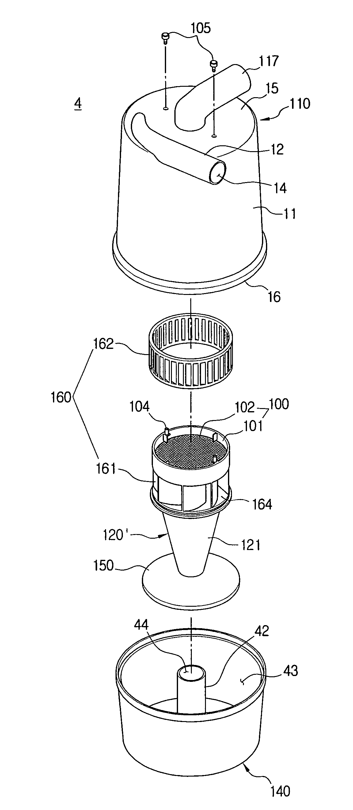
[0082]Hereinafter, a cyclone dust collecting apparatus 3 for a vacuum cleaner according to the present disclosure is described with reference to FIGS. 9 and 10.

[0083]Referring to FIGS. 9 and 10, a cyclone dust collecting apparatus 3 for a vacuum cleaner according to the third embodiment of the present disclosure includes a first cyclone 110, a second cyclone 120, a filtering member 100, and a dust collecting receptacle 140.

[0084]The first cyclone 110 is substantially the same as the first cyclone 10 of the cyclone dust collecting apparatus 1 according to the first embodiment, exception that the air-discharging pipe 117 is disposed at a top wall 15 of the first cyclone body 11. The air-discharging pipe 117 discharges purified air E passed through the filtering member 100 to the vacuum generator (not shown).

[0085]The second cyclone 120 is disposed inside the first cyclone 110. The semi-clean air C discharged from the first cyclone 110 enters to form a second downwardly whirling air cu...


PUM

PropertyMeasurementUnit
gravityaaaaaaaaaa
elasticaaaaaaaaaa
centrifugal forceaaaaaaaaaa

Abstract

The present disclosure relates to a cyclone dust collecting apparatus for a vacuum cleaner having a high fine dust collecting efficiency. The cyclone dust collecting apparatus includes a first cyclone having an air suction hole through which dust-laden air is drawn-in, the first cyclone forcing the dust-laden air to downwardly whirl in a space under the air suction hole so as to centrifugally separate dust from the dust-laden air; a second cyclone disposed inside the first cyclone, the second cyclone forcing semi-clean air entering from the first cyclone to downwardly whirl so as to centrifugally separate fine dust from the semi-clean air; and an air guiding member forcing the semi-clean air discharged from the first cyclone to directly enter the second cyclone and, the air guiding member having a plurality of guiding blades radially disposed in at least one circular shape based on a vertical axis of the second cyclone.

Description

CROSS-REFERENCE TO RELATED APPLICATIONS[0001]This application claims the benefit of U.S. provisional application No. 60 / 776,408 filed Feb. 24, 2006 in the United States Patent & Trademark Office, and claims the benefit of Korean Patent Application Nos. 2006-20961 filed Mar. 6, 2006 and No. 2006-31518 filed Apr. 6, 2006 in the Korean Intellectual Property Office, the disclosures of all of which are incorporated herein by reference in their entirety.BACKGROUND OF THE INVENTION[0002]1. Field of the Invention[0003]The present disclosure relates to a vacuum cleaner. More particularly, the present disclosure relates to a cyclone dust collecting apparatus separating and collecting dust and dirt using centrifugal force.[0004]2. Description of the Related Art[0005]Generally, the vacuum cleaner generates suction force using a motor so as to draw-in air containing dust, dirt and so on (hereinafter, referred to as dust-laden air) from a surface to be cleaned by the suction force. Dust, dirt and...

Claims


Application Information

Patent Timeline
Patent Type & Authority Patents(United States)
IPC IPC(8): B01D45/12
CPCA47L9/1633A47L9/165A47L9/1666A47L9/1683B01D45/12B01D45/16B04C5/04B04C5/14B04C5/26B04C2009/004A47L9/16A47L9/10
Inventor YOO, DONG-HUNOH, JANG-KEUNHAN, JUNG-GYUN
Owner SAMSUNG GWANGJU ELECTRONICS CO LTD
Why Eureka
Try Eureka