

Filter element
a filter element and filter element technology, applied in the field of filter elements, can solve the problems of increased filter element size, insufficient filter element dust holding capacity, and disadvantageous industrial use of filter elemen
Inactive Publication Date: 2004-11-16
HONDA MOTOR CO LTD +1
View PDF15 Cites 35 Cited by
- Summary
- Abstract
- Description
- Claims
- Application Information
AI Technical Summary
Benefits of technology
The solution significantly improves dust cleaning efficiency, extends filter lifetime, and reduces pressure loss while maintaining a low cost, effectively collecting a wide range of dust particle sizes from small carbon dust to large particles like sand.
Problems solved by technology
However, the filter element cannot sufficiently increase the dust holding capacity although the expensive nonwoven fabric is used.
Therefore, such filter element is disadvantageous to industrial use from the respect of cost-effectiveness.
In addition, if it is tried to implement the excellent dust cleaning efficiency by the dry type filter, the bulk of the filter is increased even after the improved structure such as the ridge-like-folded structure, etc. to increase the adsorption area is employed, and thus it is difficult to get the compact filter element.
However, in the wet type filter, it is known that the carbon dusts, which are caught by the oil in the filter, get out of the filter, and thus the carbon dust cannot be effectively collected.
However, if the oil is present excessively, lumps of the dust are formed at oil-excessive portions to cause the clogging.
Method used
View moreImage
Smart ImageViewing Examples

Examples
example
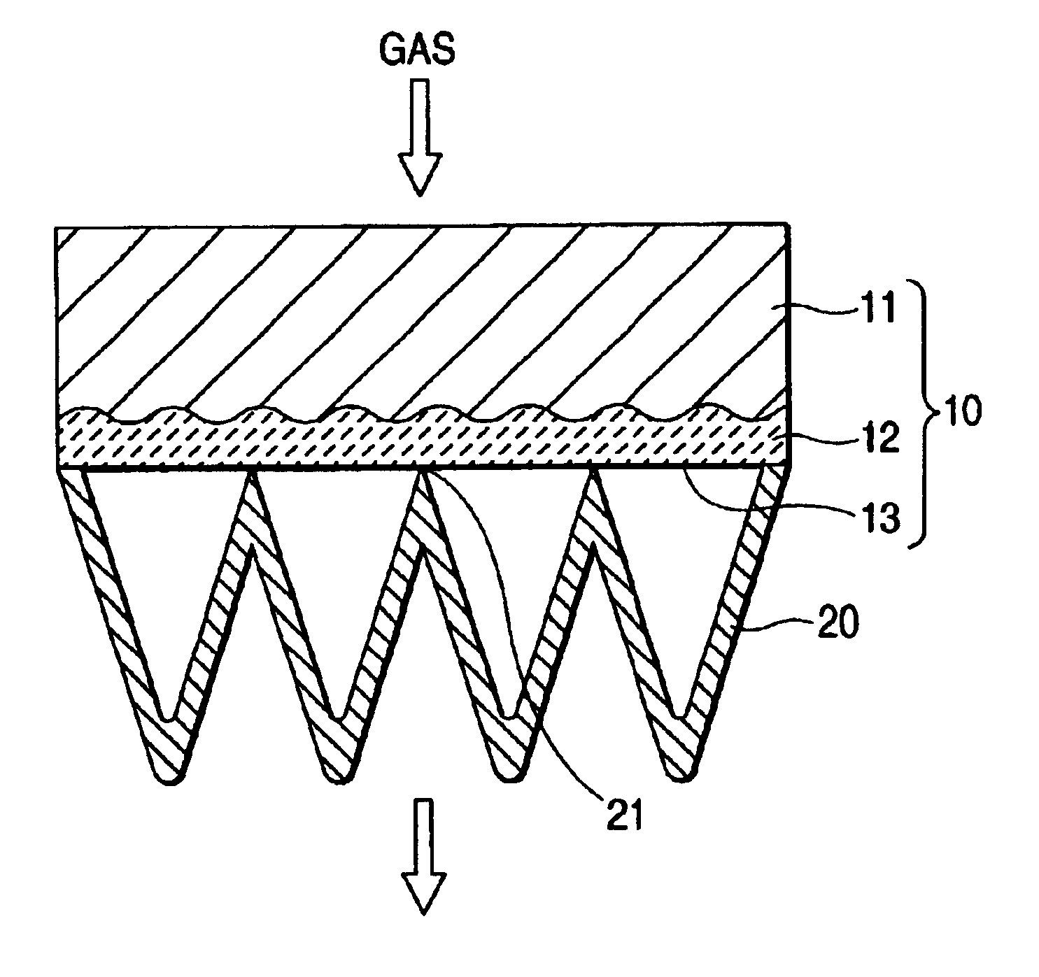
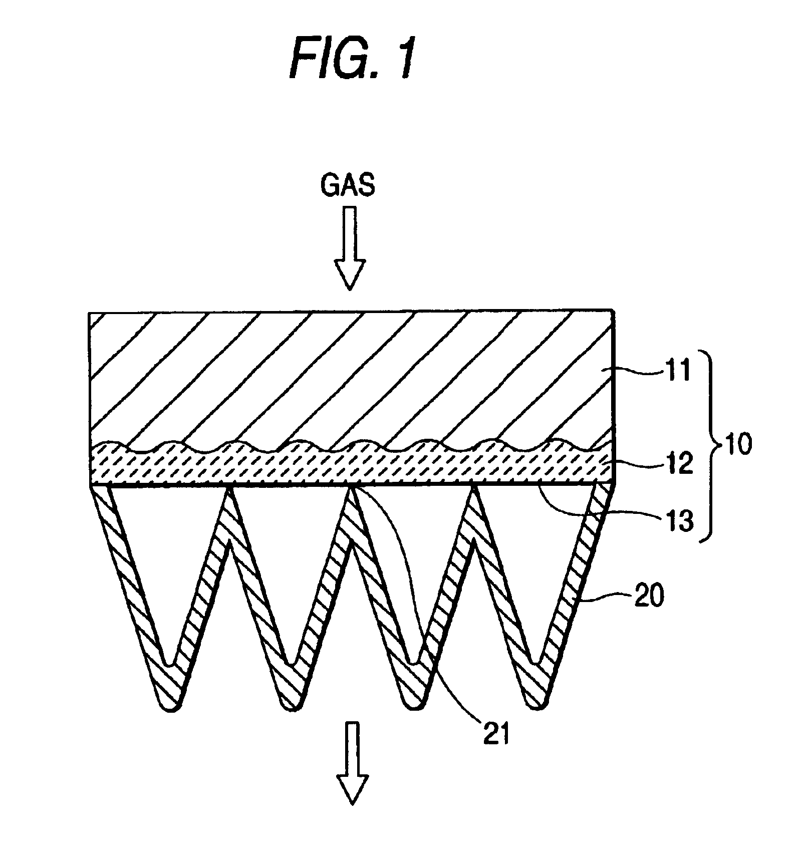
The filter element shown in FIG. 1 was obtained by arranging the second filtering member [viscous filter paper folded like the ridges (oil amount: 130 g / 54 g, kinematic viscosity of oil: 32.6 mm.sup.2 / s)] on the downstream side of the first filtering member [type (material) of nonwoven fabric: polyethylene terephthalate (PET), thickness: 18 mm, grammage: 365 g / m.sup.2 ]. This filter element was arranged so as to direct the first filtering member side toward the upstream side to accept the air-flow resistance test, the cleaning efficiency test, and the dust holding capacity test.
Login to View More PUM
| Property | Measurement | Unit |
|---|---|---|
| thickness | aaaaa | aaaaa |
| thickness | aaaaa | aaaaa |
| density | aaaaa | aaaaa |
Abstract
A filter element is made of a first filtering member, and a second filtering member that is arranged on a downstream side of the first filtering member and is impregnated with an oil. The first filtering member consists of a downstream wet layer that is impregnated with the oil, which is transferred by contact to the second filtering member, and an upstream dry layer that is not impregnated with the oil. A density of the first filtering member may be set smaller than that of the second filtering member.
Description
1. Field of the InventionThe present invention relates to a filter element that is capable of collecting carbon dusts effectively and is useful as an air cleaner, etc. of a car, an internal combustion engine, etc.2. Description of the Prior ArtIn the power source of the car, the motor bicycle, etc., the clean air is supplied to the engine by collecting the dusts by virtue of the filter element of the air cleaner in the suction system of the engine.In recent years, the filtering function of adsorbing and filtering the dusts, a particle size distribution of which extends over a wide range from the dust with a large particle size such as a cloud of sand to the dust with a small particle size such as the carbon particle contained in the exhaust gas from the diesel car, etc. (referred to as the "carbon dust" hereinafter), is required of the filter element. Also, performances such as excellent dust holding capacity (long filtering lifetime), small pressure loss, etc. are required of the f...
Claims
Login to View More Application Information
Patent Timeline
 Patent Type & AuthorityPatents(United States)
IPC IPC(8): B01D39/16B01D39/18B01D46/10F02M35/026F02M35/02F02M35/024B01D46/52
CPCB01D39/1623B01D39/18B01D46/0035B01D46/10B01D46/521F02M35/024F02M35/026Y10S55/24B01D2275/305Y10S55/05B01D2275/10
InventorTANAKA, SEIICHIYOKOYAMA, KAZUTAKAKOURA, HIROTOOKADA, TSUMORUMIZUTA, SHINSUKE
OwnerHONDA MOTOR CO LTD