Quick drainage device for ICU nurse

A fast, drainage tube technology, applied in the direction of suction equipment, other medical equipment, catheters, etc., to achieve efficient and smooth drainage, solve end blockage, and small expansion resistance

Inactive Publication Date: 2018-08-17
陈海红
View PDF5 Cites 2 Cited by
  • Summary
  • Abstract
  • Description
  • Claims
  • Application Information

AI Technical Summary

Problems solved by technology

A more comprehensive and effective solution to the problem of end face and inlet blockage, can more effectively expand the narrow area of ​​the human body, and reduce entry resistance

Method used


Image

  • Quick drainage device for ICU nurse
  • Quick drainage device for ICU nurse
  • Quick drainage device for ICU nurse

Examples


Embodiment Construction

[0028] The present invention will be further described in detail below in conjunction with the accompanying drawings and specific embodiments.

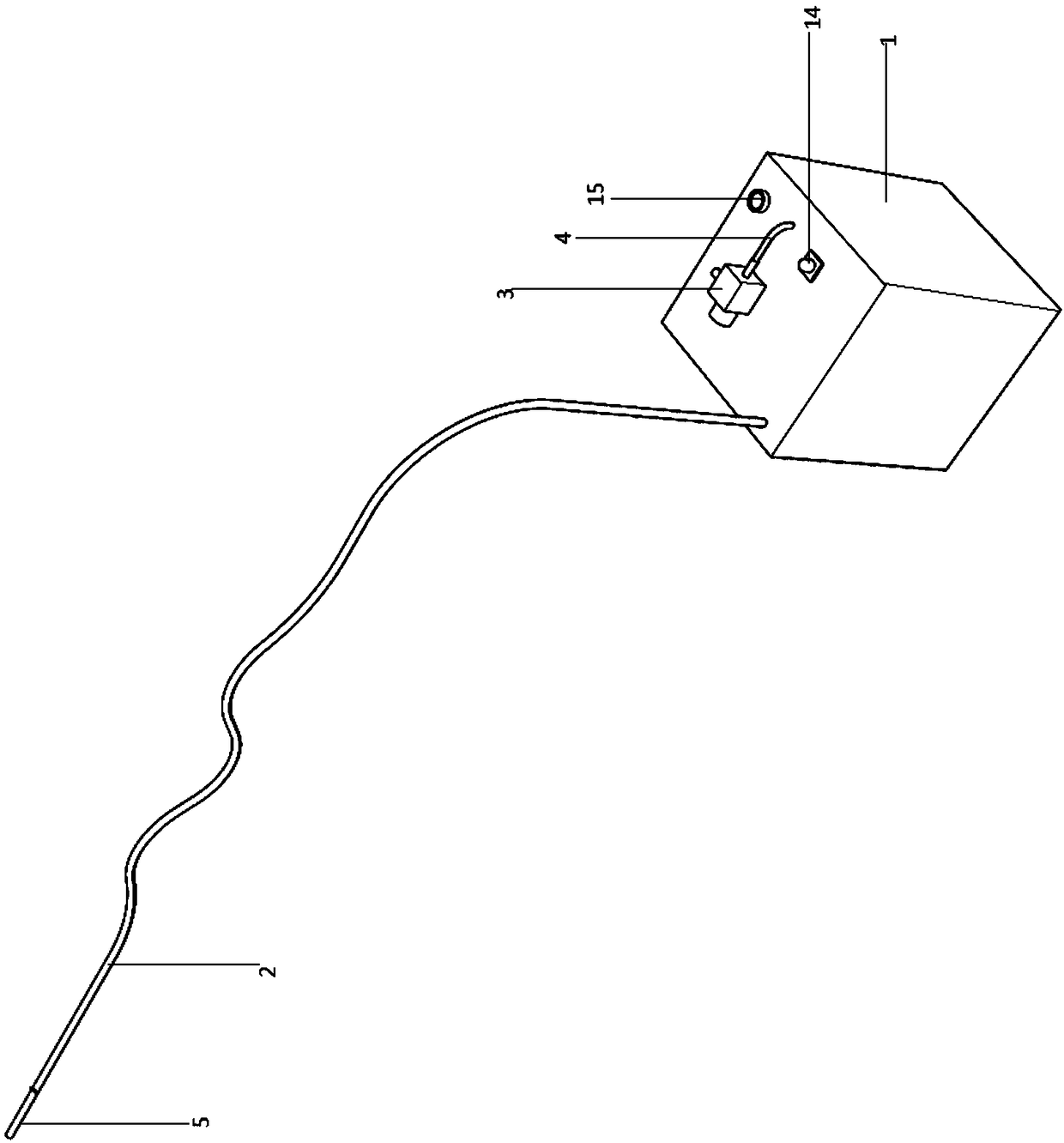
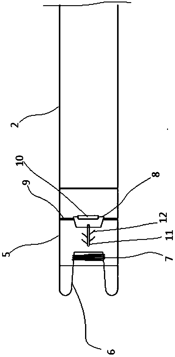
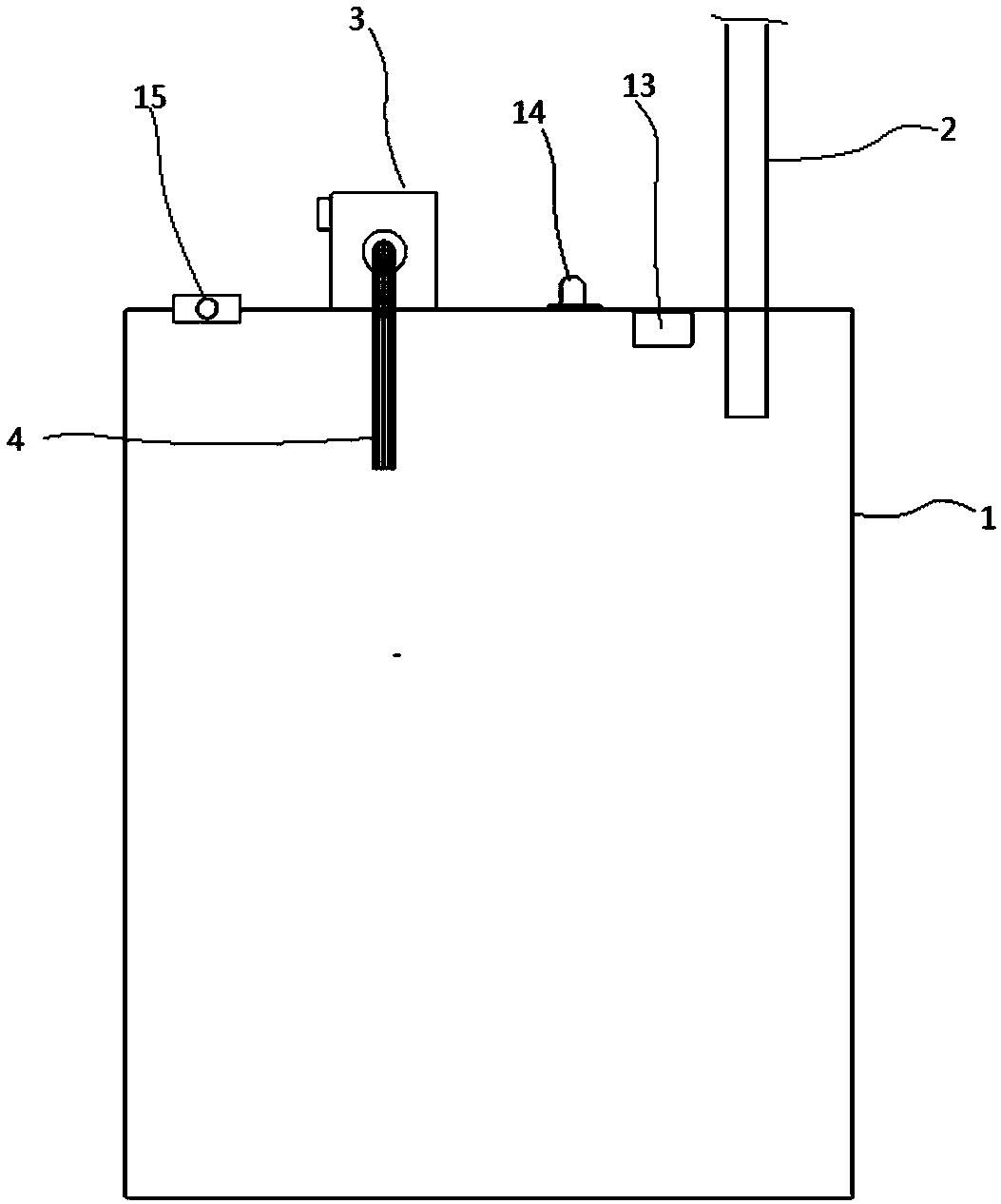
[0029] Such as Figure 1-6 As shown, a rapid drainage device for ICU care includes a collection box 1; a drainage tube 2 is connected to the upper end of the collection box 1; an anti-blocking device is installed on the drainage tube 2; a negative pressure pump 3 is installed on the upper end of the collection box 1; The suction end of the pump 3 is connected with a suction pipe 4; the other end of the suction pipe 4 communicates with the collection box 1; the anti-blocking device includes a pipe head 5 communicating with the top of the drainage pipe 2; the left end of the pipe head 5 is fixedly connected with an elastic Sleeve 6; the elastic sleeve 6 is in the left part of the pipe head 5; the left end of the elastic sleeve 6 is docked with the left end of the pipe head 5; 7 is sealed in the wall of the right part of the elastic sle...


PUM


Abstract

The invention discloses a quick drainage device for ICU nurse, and relates to the technical field of ICU critical care. The quick drainage device comprises a collecting box; a drainage pipe is communicated with the upper end of the collecting box; an anti-blocking device is installed on the drainage pipe; the anti-blocking device comprises a pipe head communicated with the top of the drainage pipe; an elastic casing pipe is fixedly connected to the left end of the pipe head; the left end of the elastic casing pipe is in butt joint with the left end of the pipe head; an electromagnetic coil fixedly sleeves the outer side of the right portion of the elastic casing pipe; a mounting column is arranged at the right portion in the pipe head; a permanent magnet is installed at the right end of the mounting column; a puncture rod is installed at the left end of the mounting column; an air pressure sensor module is installed in the collecting box; the signal output end of the air pressure sensor module is connected with a processor; the output end of the processor is connected with a control circuit of a negative pressure pump and the electromagnetic coil. The quick drainage device has theadvantages that the problem that the end face and an inlet are blocked is more comprehensively and more effectively solved, the narrow area of the human body can be more effectively expanded, and theentering resistance is reduced.

Description

technical field [0001] The invention relates to the technical field of ICU intensive medical care. Background technique [0002] In the existing ICU nursing, it is often necessary to drain the patient's effusion during or after the operation, and the general drainage device uses negative pressure and a drainage tube to perform the drainage operation, but when draining in the body, the end of the drainage tube The problem of clogging at the inlet has never been solved well. The general solution is to prevent clogging by adding a filter device, but it cannot fundamentally solve the problem. The filter device still needs to be replaced or even completely blocked and unable to work properly during use. In effusion drainage, the general blockages are clots or viscous substances, etc., which are easy to cause blockage if they are sucked into the end. Therefore, it is necessary to be able to effectively treat them to prevent blockage and ensure efficient drainage. At the same time...

Claims


Application Information

Patent Timeline
IPC IPC(8): A61M1/00A61M25/00
CPCA61M1/0023A61M25/0074A61M25/0082A61M2025/0002A61M2205/10A61M2205/33A61M1/84A61M1/88
Inventor 张小飞王莹聂明斐
Owner 陈海红
Why Eureka
Try Eureka