In-situ protection of pressure pipelines crossing deep foundation pits and retaining structures and construction methods

A technology for retaining structures and deep foundation pits, which can be used in infrastructure engineering, excavation, construction, etc., to solve problems such as inability to meet on-site construction and failure to achieve reinforcement effects, and to reduce the possibility of water seepage, water leakage, landslides, and thickness reduction. , the effect of good piling effect

Active Publication Date: 2020-06-16
URBAN MASS TRANSIT ENG CO LTD OF CHINA RAILWAY 11TH BUREAU GRP +1
View PDF5 Cites 0 Cited by
  • Summary
  • Abstract
  • Description
  • Claims
  • Application Information

AI Technical Summary

Problems solved by technology

However, the foundation pit here is an ultra-deep foundation pit with an excavation depth of 26m, and the stratum is also a high standard penetration stratum with a standard penetration of more than 45. , can hardly achieve any reinforcement effect, and cannot meet the requirements of on-site construction, and the importance of the pipeline above the enclosure structure also puts forward almost strict requirements on the deformation and displacement of the pipeline during the reinforcement process

Method used


Image

  • In-situ protection of pressure pipelines crossing deep foundation pits and retaining structures and construction methods
  • In-situ protection of pressure pipelines crossing deep foundation pits and retaining structures and construction methods

Examples


Embodiment Construction

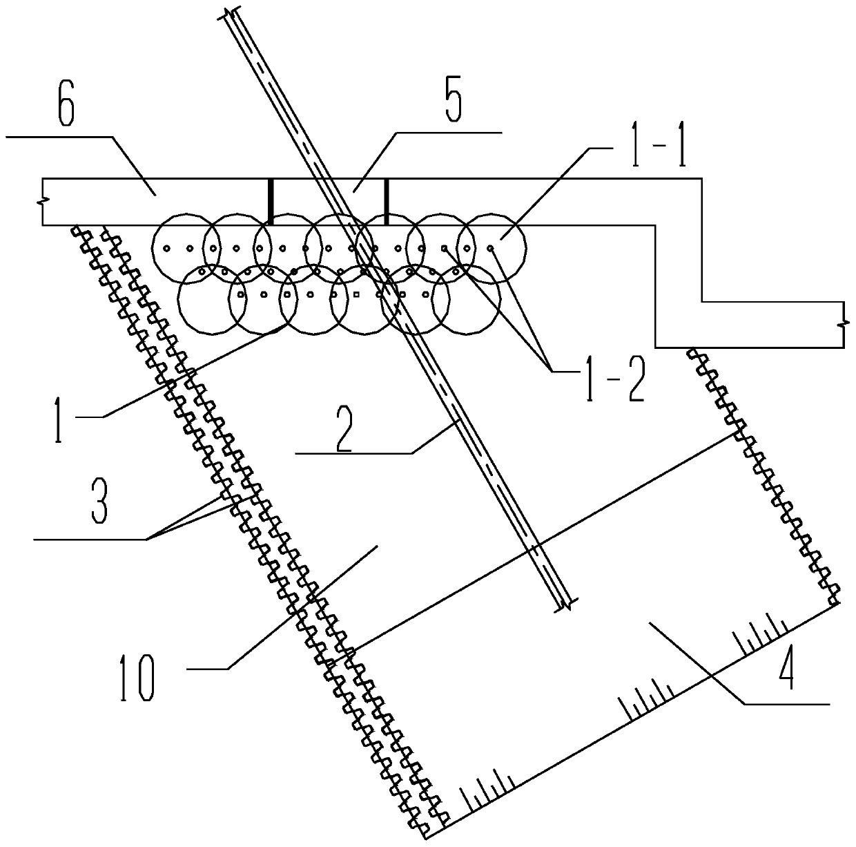
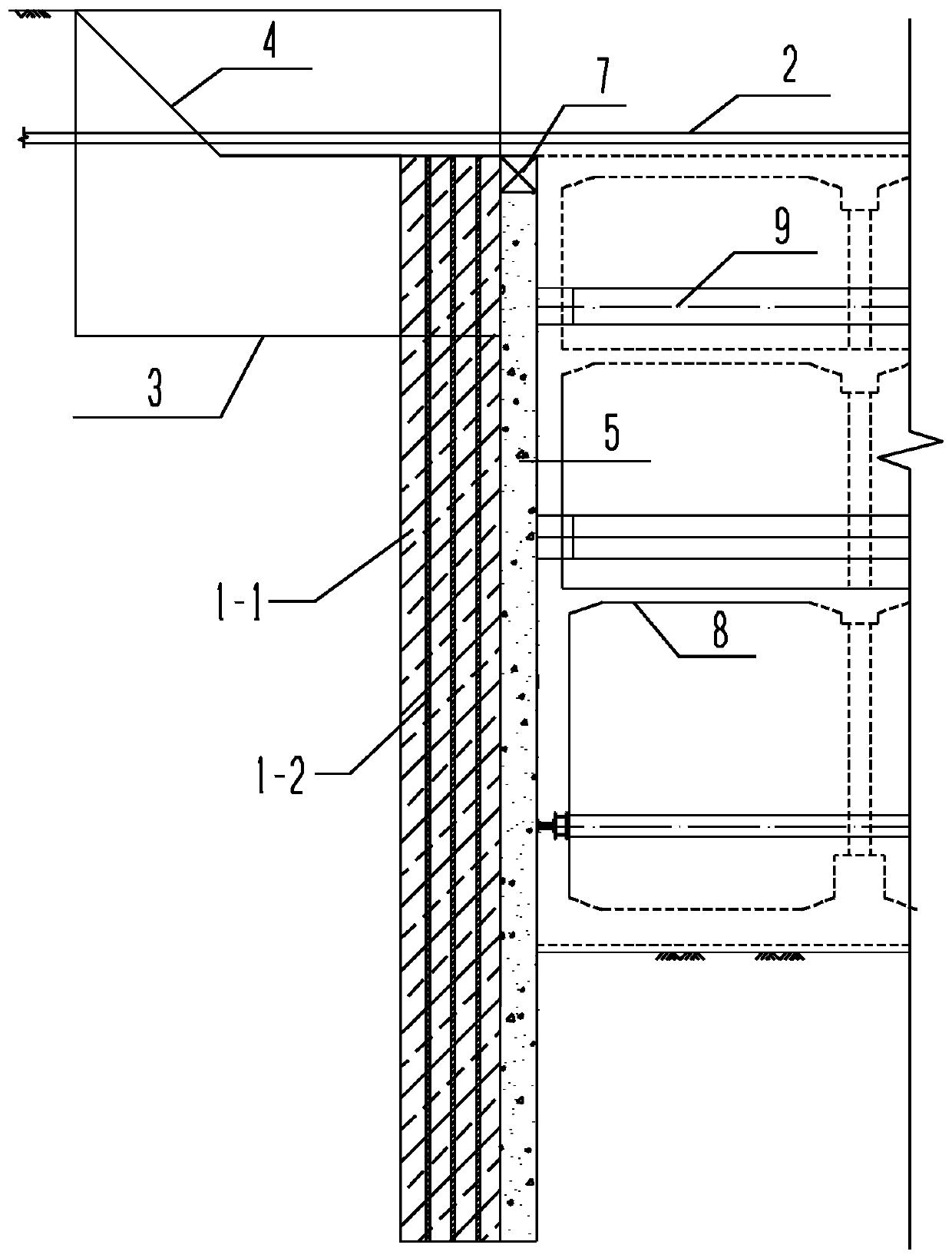
[0031] The present invention will be further described below in conjunction with drawings and embodiments. like figure 1A kind of in-situ protection and enclosure retaining structure for pressure pipelines crossing deep foundation pits shown, including the first-stage underground diaphragm wall 6 constructed on both sides of the in-situ protection pipeline 2, the first-stage underground diaphragm wall 6 An interruption area 5 is formed near the pipeline 2 to be protected in situ, the width of the interruption area 5 is not greater than 2.5m, and a gap greater than 0.5m is reserved between the two sections of the interruption area 5 and the pipeline 2 to be protected in situ, The underground diaphragm wall at the interrupted area is constructed by the reverse method. Before the construction, the retaining structure is constructed, and a retaining wall construction area 10 is dug outside the interrupted area 5. The width of the retaining wall construction area 10 is greater than...


PUM


Abstract

The invention provides a structure for in-situ protection of a pressure pipeline transversely penetrating through a deep foundation pit and surrounding soil-retaining and a construction method. The construction process of the soil-retaining structure comprises the steps that firstly, a first-stage underground continuous wall is constructed on the two sides of the pipeline to be protected in situ,the first-stage underground continuous wall is broken off at the position close to pipeline to be protected in situ, then a steel sheet pile supporting structure and a composite pile retaining wall are constructed on the outer side of the first-stage underground continuous wall, wherein the composite pile retaining wall is arranged on the outer side of the breaking region, is composed of MJS jet grouting pile reinforcing bodies composed of multiples mutually-occlusive MJS jet grouting piles and multiples micro steel pipe piles inserted into the MJS jet grouting pile reinforcing bodies, and isused for completely shielding the breaking region, and the steel sheet pile supporting structure is composed of two rows of steel sheet piles constructed on the two sides of the composite pile retaining wall. According to the structure and the construction method, the influence on the environment is greatly reduced, before the foundation pit is excavated, the effect of closing the surrounding structure is achieved, the possibility that water seepage, water leakage and collapse occur at a continuous wall reverse-constructing position when the foundation pit is excavated is effectively reduced,and the safety coefficient during foundation pit excavating and continuous wall reverse constructing is increased.

Description

technical field [0001] The invention relates to the field of in-situ pipeline protection for underground structure construction, in particular to a construction method for in-situ protection of pressure pipelines and enclosing soil retaining structures suitable for high standard penetration strata crossing deep foundation pits. Background technique [0002] With the upgrading and transformation of urbanization, the infrastructure construction of urbanization in our country is accelerated, especially the construction of urban subway rail transit is becoming more and more rapid. The construction of subway will inevitably have a great impact on the original various municipal pipelines, and the original The layout of planned and under-construction pipelines brings inconvenience, and the problems of pipeline relocation and how to protect existing pipelines have become difficult problems in subway construction. [0003] Pipelines in some special areas cannot be relocated at will. ...

Claims


Application Information

Patent Timeline
Patent Type & Authority Patents(China)
IPC IPC(8): E02D17/04
CPCE02D17/04
Inventor 李应姣张志冰彭刚龙华东谭桂平周坤李杰曹铁军田诗国
Owner URBAN MASS TRANSIT ENG CO LTD OF CHINA RAILWAY 11TH BUREAU GRP
Why Eureka
Try Eureka