A Length Compensation Method for Cutting Profiles Cut by Cutting Machine Tools

A technology of length compensation and cutting machine tools, applied in computer control, program control, instruments, etc., can solve the problems of high requirements and limitations of machine tools and CNC systems, improve machining accuracy and machining efficiency, optimize cutting force error, and improve machining. precise effect

Active Publication Date: 2020-11-03
佛山金皇宇企业孵化器有限公司 +1
View PDF6 Cites 0 Cited by
  • Summary
  • Abstract
  • Description
  • Claims
  • Application Information

AI Technical Summary

Problems solved by technology

The compensation accuracy is high, but the requirements for machine tools and CNC systems are also high, subject to certain restrictions

Method used


Image

  • A Length Compensation Method for Cutting Profiles Cut by Cutting Machine Tools
  • A Length Compensation Method for Cutting Profiles Cut by Cutting Machine Tools
  • A Length Compensation Method for Cutting Profiles Cut by Cutting Machine Tools

Examples


Embodiment Construction

[0047] In order to further understand the features, technical means, and specific objectives and functions of the utility model, the utility model will be further described in detail below in conjunction with the accompanying drawings and specific embodiments.

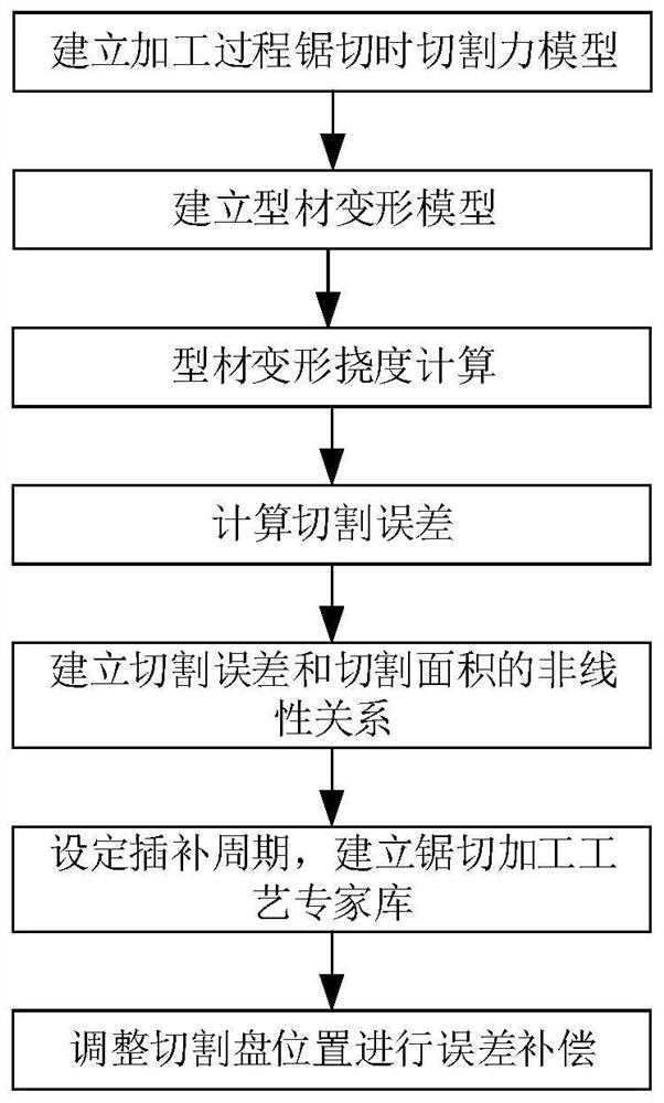
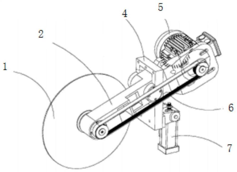
[0048] as attached Figure 1-3 As shown, the present invention discloses a length compensation method for sawing profiles by a cutting machine, comprising the following steps:

[0049] S1, establishing a cutting force model during sawing during processing.

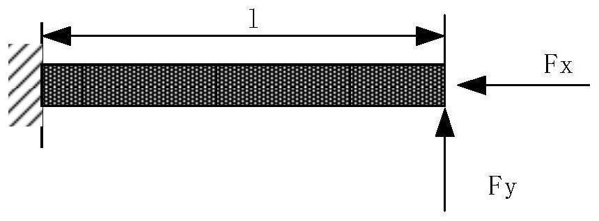
[0050] S2, establishing the aluminum profile deformation model.

[0051] S3, setting the interpolation period, and establishing a sawing process expert database according to the known aluminum profile information and the nonlinear relationship between the cutting error and the cutting area. The relationship between cutting error and cutting area is non-linear, that is, the larger the cutting area, the smaller the cutting error.

[0052] S4, plan the cutting traj...


PUM


Abstract

The present invention discloses a length compensation method of saw cutting of section bars through a cutting machine. The method comprises the following steps of: S1, establishing a cutting force model when sew cutting is performed in a processing process; S2, establishing a section aluminum deformation model; S3, setting an interpolation period, and establishing a saw cutting processing technology expert database according to known section aluminum information, cutting errors and cutting areas; and S4, performing cutting track planning according to the saw cutting processing technology expert database to perform error compensation of the position of a cutting disc and complete processing. The method effectively improves the processing accuracy and improves the processing quality.

Description

technical field [0001] The invention belongs to the technical field of sawing processing, and more specifically relates to a length compensation method for sawing profiles by a cutting machine tool. Background technique [0002] The sources of processing errors in sawing processing can be divided into constant value system errors and variable system errors according to the causes of processing errors. The constant value system error includes the manufacturing error of the machine tool-tool-fixture, the wear error of each component of the machine tool and the error of the machining principle. The variable value system error includes the error caused by the deformation caused by tool wear, heat and force. The error caused by sawing force and the error caused by thermal deformation are the main reasons for the length error of sawing profiles. [0003] In order to ensure the accuracy of the machined surface, there are two common ways to reduce and eliminate errors: error avoid...

Claims


Application Information

Patent Timeline
Patent Type & Authority Patents(China)
IPC IPC(8): G05B19/404
CPCG05B19/404G05B2219/33002G05B2219/45003G05B2219/45044G05B2219/45144
Inventor 周俊伍
Owner 佛山金皇宇企业孵化器有限公司
Why Eureka
Try Eureka