Thyroid gland neck tissue classifying and identifying system and method based on autofluorescence technology and optical coherence tomography

An optical coherence tomography and autofluorescence technology, which is used in the analysis of fluorescence emission, medical science, and diagnosis using tomography, etc. It can solve the problems of small imaging range and inability to quickly locate the parathyroid glands.

Pending Publication Date: 2018-09-14
NANKAI UNIV
View PDF6 Cites 6 Cited by
  • Summary
  • Abstract
  • Description
  • Claims
  • Application Information

AI Technical Summary

Problems solved by technology

For thyroid neck tissue imaging, the problem with optical coherence tomography is that the imaging range is small and the parathyroid glands cannot be quickly located

Method used


Image

  • Thyroid gland neck tissue classifying and identifying system and method based on autofluorescence technology and optical coherence tomography
  • Thyroid gland neck tissue classifying and identifying system and method based on autofluorescence technology and optical coherence tomography
  • Thyroid gland neck tissue classifying and identifying system and method based on autofluorescence technology and optical coherence tomography

Examples


Embodiment 1

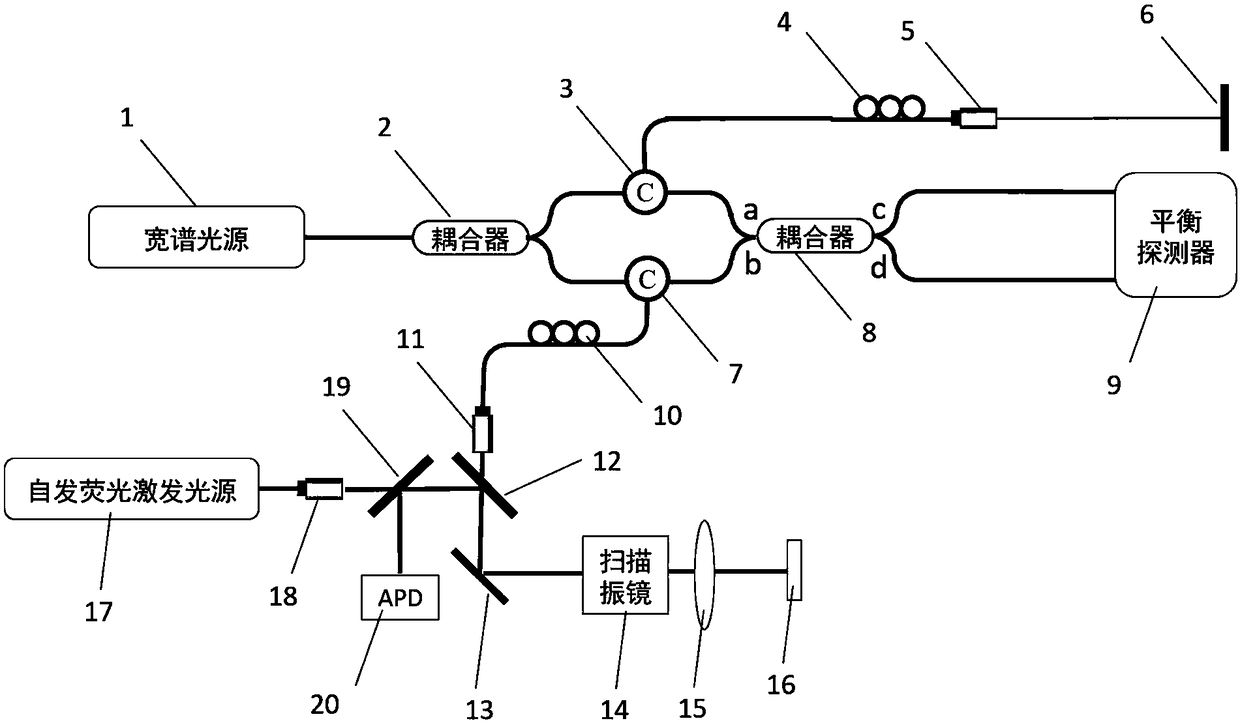
[0032] For the TD-OCT and AF dual-mode imaging system and SS-OCT and AF dual-mode imaging system, the system hardware includes: 1300nm or 1550nm wide-spectrum light source (1), the first coupler (2), the first circulator (3 ), the first polarization controller (4), the first collimator (5), the first mirror (6), the second circulator (7), the second coupler (8), the balance detector (9) , the second polarization controller (10), the second collimator (11), the first dichroic mirror (12), the second reflection mirror (13), the scanning galvanometer (14), the first focusing mirror (15 ), sample stage (16), adopt 780nm LED or 785nm laser or other light sources covering 780nm as autofluorescence excitation light source (17), third collimator (18), second dichroic mirror (19), photoelectric detector (20);

[0033] Among them, the broadband light source (1), the first coupler (2), the first circulator (3), the first polarization controller (4), the first collimator (5), and the fir...

Embodiment 2

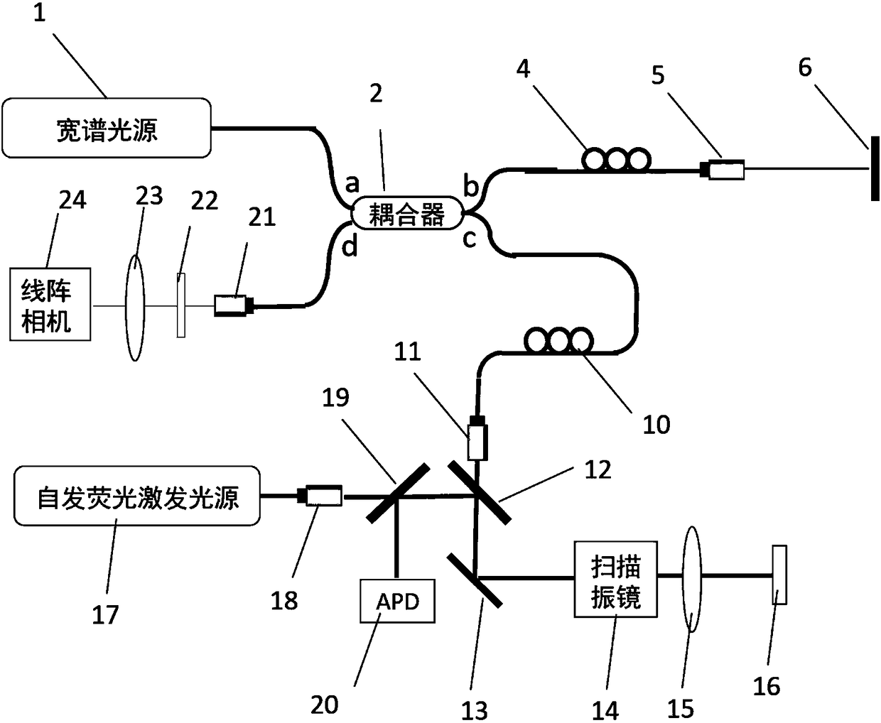
[0039] For the SD-OCT and AF dual-mode imaging system, the system hardware includes: 1300nm or 1550nm wide-spectrum light source (1), the first coupler (2), the first polarization controller (4), the first collimator (5 ), the first mirror (6), the fourth collimator (21), the grating (22), the second focusing mirror (23), the line scan camera (24), the second polarization controller (10), the second Collimator (11), first dichroic mirror (12), second reflector (13), scanning galvanometer (14), first focusing mirror (15), sample stage (16), LED with 780nm Or 785nm laser or other light source covering 780nm as autofluorescence excitation light source (17), third collimator (18), second dichroic mirror (19), photodetector (20);

[0040] Wherein, the wide-spectrum light source (1), the first coupler (2), the first polarization controller (4), the first collimator (5), the first mirror (6), the fourth collimator (21 ), grating (22), second focusing mirror (23), line scan camera (2...


PUM


Abstract

Provided are a thyroid gland neck tissue classifying and identifying system and method based on an autofluorescence technology and an optical coherence tomography. The system organically integrates anautofluorescence system and an optical coherence tomography system, utilizes high-sensitivity tissue element resolution capability of the autofluorescence system and high-resolution tissue structureimaging of the optical coherence tomography system to achieve quick, identifier-free, nondestructive, high-sensitivity and real-time thyroid gland neck tissue classification and identification. By adopting the thyroid gland neck tissue classifying and identifying system and method, the classification and identification efficiency and accuracy of doctors to parathyroid glands, thyroid glands, fat,lymph glands and other neck tissues in clinic thyroid gland operation can be effectively improved, the doctors can be assisted to protect the parathyroid glands and thoroughly remove the lymph glands.

Description

technical field [0001] The present invention relates to a dual-mode imaging system and method, especially a system and method based on autofluorescence technology and optical coherence tomography that can be used for thyroid neck tissue classification and identification, and is a new system for thyroid neck tissue imaging A method and a method belong to the technical field of biological tissue imaging. Background technique [0002] In recent years, the incidence of thyroid cancer has been increasing year by year. Partial or total thyroidectomy is the best option for most malignant and some benign thyroid lesions. To prevent recurrence of the neoplastic lesion, the surrounding lymph nodes are usually dissected. In thyroid surgery, parathyroid protection is required to prevent postoperative hypocalcemia. However, due to the small size of the parathyroid glands (3-8 mm in length, 2-5 mm in width, and 0.5-2 mm in thickness), the number and location are not completely determin...

Claims


Application Information

Patent Timeline
Patent Type & Authority Applications(China)
IPC IPC(8): A61B5/00
CPCA61B5/0035A61B5/004A61B5/0071A61B5/0073
Inventor 梁艳梅侯方于洋高明
Owner NANKAI UNIV
Why Eureka
Try Eureka