Roller type wedge transverse rolling machine directly driven by frameless permanent magnet synchronous motor

The technology of permanent magnet synchronous motor and cross wedge rolling mill is applied in the driving device, magnetic circuit, electromechanical device and other directions of metal rolling mill, which can solve the problems of large power loss, inconvenience in precise processing of rolling parts, low transmission accuracy, etc. Achieve the effect of reducing manufacturing cost, fast response speed and high control precision

Pending Publication Date: 2018-09-21
HUBEI HUANYEE ELECTROMAGNETIC EQUIP ENG TECH CO LTD
View PDF0 Cites 0 Cited by
  • Summary
  • Abstract
  • Description
  • Claims
  • Application Information

AI Technical Summary

Problems solved by technology

At present, the cross-wedge rolling mill is the most widely used, and the cross-wedge rolling mill has two types of two-roller and three-roller. There are many intermediate transmission parts, the power loss is large, and the transmission accuracy is low, which is not convenient for precise processing of rolling parts

Method used


Image

  • Roller type wedge transverse rolling machine directly driven by frameless permanent magnet synchronous motor
  • Roller type wedge transverse rolling machine directly driven by frameless permanent magnet synchronous motor
  • Roller type wedge transverse rolling machine directly driven by frameless permanent magnet synchronous motor

Examples


Embodiment 1

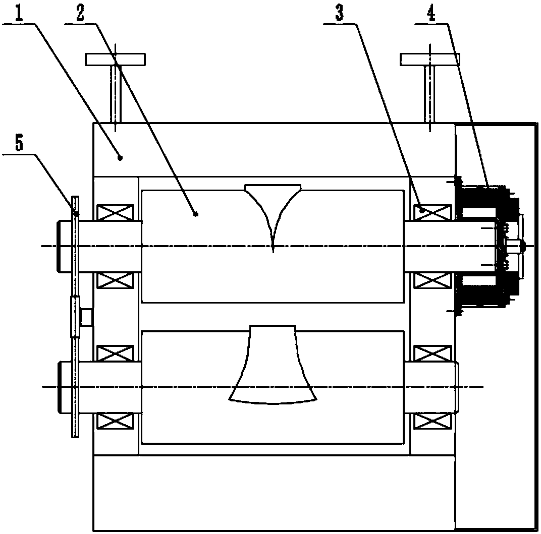
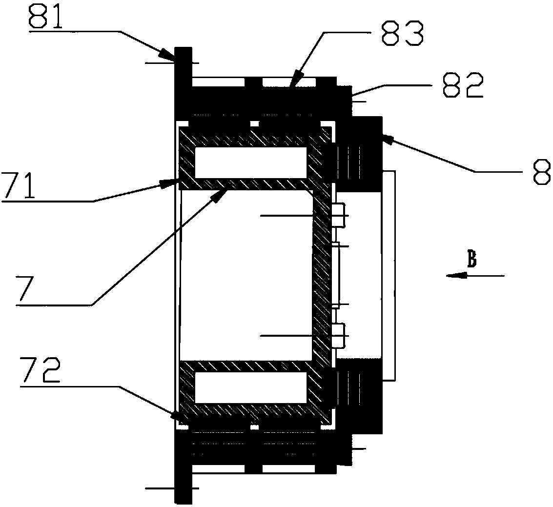
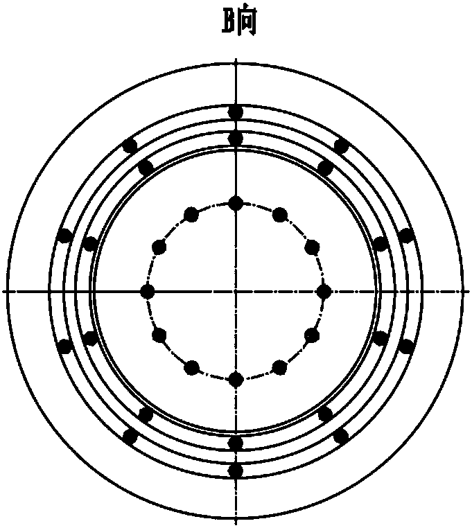
[0038] Such as Figure 1-5 As shown, this embodiment provides a frameless permanent magnet synchronous motor direct-driven roller cross wedge rolling mill, which includes a working rolling mill and a driving motor for driving the working rolling mill, and the working rolling mill includes a rolling mill Frame 1, two rolls 2 and support bearings 3 for supporting the rolls 2; the input end of the rolls 2 is directly driven by the drive motor; each of the rolls 2 and the rolling mill stand 1 There are support bearings 3 between them; the drive motor is a frameless permanent magnet synchronous motor 4, including a rotor assembly 7 and a stator assembly 8; wherein, the stator assembly 8 is opposite to the rotor assembly 7, and the stator assembly 8 A rotating magnetic field is provided to drive the rotor assembly 7 to rotate; the stator assembly 8 is fixedly connected to the rolling mill frame 1, and the rotor assembly 7 is fixedly connected to one of the rolls 2; the stator assemb...

Embodiment 2

[0042] Such as Image 6 As shown, the preferred embodiment of the present invention is to provide a frameless permanent magnet synchronous motor direct-driven roller type cross wedge rolling mill. The difference is that the cross wedge rolling mill in this embodiment is driven by two machines, and the number of the frameless permanent magnet synchronous motors 4 is the same as the number of the rolls 2; each of the frameless permanent magnet synchronous The motors 4 are fixedly connected to the input ends of the rolls 2 . Wherein, the cross wedge rolling mill includes two rolls 2, each of which is connected with a frameless permanent magnet synchronous motor 4 at the input end. The double motors work together to ensure the precise forming of the workpiece during rolling.

Embodiment 3

[0044] Such as Figure 7-9 As shown, the preferred embodiment of the present invention is to provide a frameless permanent magnet synchronous motor direct-driven roller type cross wedge rolling mill. The structure and working principle of this embodiment are similar to those of embodiment 1 or 2. The difference between 1 and 2 is that there is an air gap 6 between the stator base and the rotor base in this embodiment, and the two ends of the air gap 6 are respectively provided with at least two layers of seals arranged in parallel. Ring 61; the outer ring and the inner ring of the sealing ring 61 have a hook-shaped structure 62, and elastic balls 63 distributed in a ring are embedded in the connection between the hook-shaped structure 62 and the body of the sealing ring 61; The free ends of the hook structures 62 are located in the spaces formed by the plurality of sealing rings 61 , and the hook structures 62 are alternately in free contact with the stator base and the rotor ...


PUM


Abstract

The invention discloses a roller type wedge transverse rolling machine directly driven by a frameless permanent magnet synchronous motor. The machine comprises a drive motor, a rolling machine rack, aroller and a supporting bearing used for supporting the roller. The drive motor is the frameless permanent magnet synchronous motor and comprises a rotor assembly and a stator assembly which are opposite. The stator assembly is fixedly connected to the rolling machine rack. The rotor assembly is fixedly connected with the roller. A stator iron core in the stator assembly is in a ring-shaped structure formed in an integral machining manner. A stator winding is wound in the stator iron core. According to the machine, the rotor assembly is directly connected with the roller, a power part servesas an active cell of the motor, the motor and a mechanical part are integrated, the drive middle links such as a gear and a speed reduction box are reduced, the drive manner and the structure are simplified, the drive efficiency is improved, and the loss of energy sources is reduced.

Description

technical field [0001] The invention relates to the field of forging machinery and equipment, in particular to a roll cross wedge rolling mill directly driven by a frameless permanent magnet synchronous motor. Background technique [0002] Cross-wedge rolling technology A steel rolling technology that appeared in 1961, it is suitable for rolling variable-section rotary bodies. It uses two wedge-shaped dies installed on the co-rotating rolls to make the blank produce continuous local deformation, and finally roll it into various stepped shaft parts. This technology is widely used in the production of various parts with rotating bodies because of its high efficiency, material saving, energy saving and other characteristics. At present, the cross-wedge rolling mill is the most widely used, and the cross-wedge rolling mill has two types of two-roller and three-roller. There are many intermediate transmission parts, the power loss is large, and the transmission accuracy is low,...

Claims


Application Information

Patent Timeline
IPC IPC(8): B21B35/00H02K1/16H02K1/20H02K1/27H02K5/10H02K7/116
CPCH02K1/16H02K1/20H02K1/2706H02K5/10H02K7/116B21B35/00
Inventor 黄诚杨勇强
Owner HUBEI HUANYEE ELECTROMAGNETIC EQUIP ENG TECH CO LTD
Why Eureka
Try Eureka