Composite crusher directly driven by permanent magnet synchronous motor

A technology of permanent magnet synchronous motor and compound crusher, which is applied in the direction of electrical components, electromechanical devices, grain processing, etc. It can solve the problems that the impact plate of the crusher is easy to be worn, the manufacturing cost is increased, and the installation is inconvenient, etc., and the drive can be simplified The method and structure, the effect of reducing the volume and prolonging the service life

Pending Publication Date: 2019-06-07
HUBEI HUANYEE ELECTROMAGNETIC EQUIP ENG TECH CO LTD
View PDF1 Cites 1 Cited by
  • Summary
  • Abstract
  • Description
  • Claims
  • Application Information

AI Technical Summary

Problems solved by technology

However, this device still does not solve the problem of large power loss in the motor drive process, and ensures good sealing performance. Its design is a relatively complicated sealing structure, but this will lead to increased manufacturing costs and is also inconvenient to install; and its crusher The impact plate is easy to be worn and inconvenient to replace

Method used


Image

  • Composite crusher directly driven by permanent magnet synchronous motor
  • Composite crusher directly driven by permanent magnet synchronous motor
  • Composite crusher directly driven by permanent magnet synchronous motor

Examples


Embodiment 1

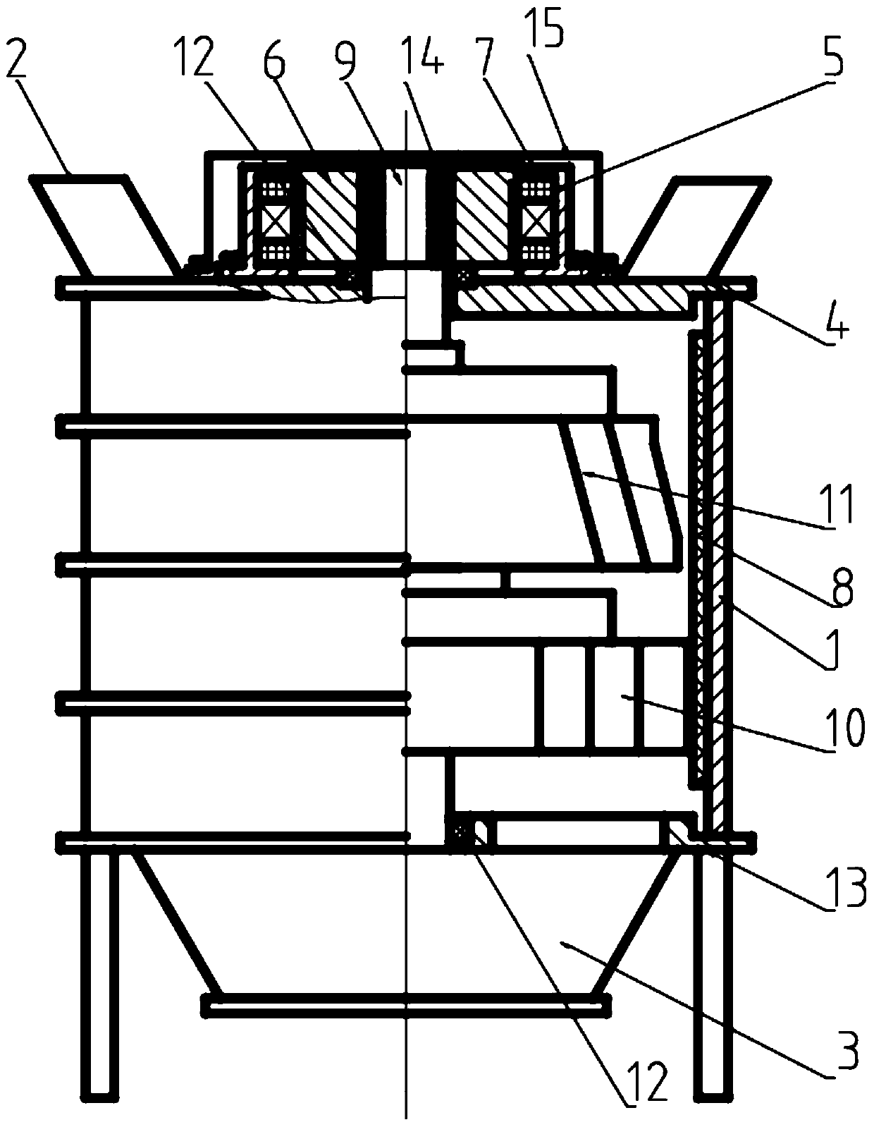
[0036] A compound crusher directly driven by a permanent magnet synchronous motor in this embodiment, combined with Figure 1 to Figure 4 Be explained:

[0037] A compound crusher directly driven by a permanent magnet synchronous motor, comprising a cylinder body 1, a plurality of feed ports 2 are arranged above the cylinder body, and the plurality of feed ports are evenly arranged on a machine cover 4 in a ring around the motor; A discharge port 3 is provided under the cylinder body 1; a lining plate 8 is provided on the inner wall of the cylinder body 1, and the lining plate 8 is a high-strength steel tooth plate; the cylinder body 1 is provided with a main shaft 9 whose rotation axis extends up and down, and the main shaft 9 is provided with two rotors, the gap between the outer end of the lower rotor 10 and the lining plate is smaller than the gap between the outer end of the upper rotor 11 and the lining plate 8; The above permanent magnet synchronous motor 5 is directly...

Embodiment 2

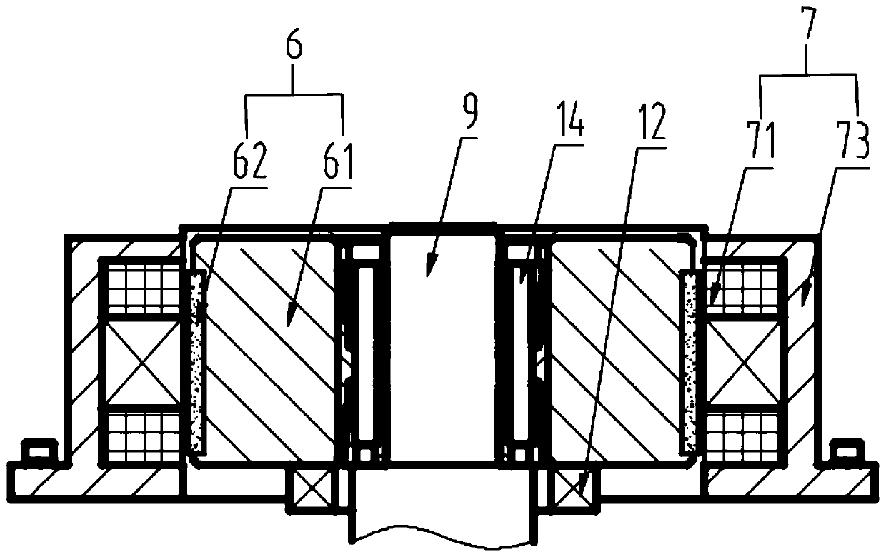
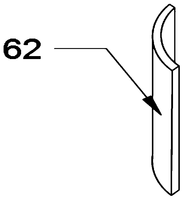
[0043] This embodiment is basically the same as Embodiment 1, and the differences are combined Figure 5 ~ Figure 8 To illustrate: the permanent magnets include two groups of permanent magnets 1 62 and 2 63 on the outer end surface of the rotor base 61 respectively; The first stator base 73 and the second stator base 74 are sleeved, and the first stator base 73 and the second stator base 74 are respectively provided with the stator core of the annular column stator core 71 and the annular disk. Two 72, the first stator base 73 is fixed on the machine cover by bolts, and the second stator base 74 is fixed on the first stator base 73 by bolts.

[0044] After electrification, stator core 1 71 provides a radially rotating magnetic field for permanent magnet 1 62, while stator core 2 72 provides an axially rotating magnetic field for permanent magnet 2 63, prompting stator assembly 7 to provide rotor assembly 6 with The moment of rotation around the axis of the main shaft 9 direct...

Embodiment 3

[0047] This embodiment is basically the same as Embodiment 2, and the differences are combined Figure 9-10 To illustrate: the liner 8 is composed of a plurality of I-shaped high-manganese steel plates that are integrally processed and formed. The I-shaped liner includes a connecting block in the middle and counter-attacking blocks with sharp ends at both ends.

[0048] The liner 8 is installed inside the barrel through a fixing frame 16, the fixing frame 16 includes an upper fixing ring 161 and a lower supporting frame 162, and the upper fixing ring is provided with a plurality of holes for fixing one end of the I-shaped liner 8. Socket, the lower support frame is used to support the bottom surface of the I-shaped liner.


PUM


Abstract

The invention discloses a composite crusher directly driven by a permanent magnet synchronous motor. The composite crusher comprises a barrel body, a lining plate is arranged on the inner wall of thebarrel body, a main shaft with the rotating axis extending in the up-down direction is arranged in the barrel body, at least one rotor is arranged on the main shaft, the upper portion of the main shaft penetrates through a machine cover above the barrel body, moreover, the main shaft is directly driven by the permanent magnet synchronous motor on the machine cover, wherein the permanent magnet synchronous motor comprises a rotor assembly and a stator assembly which are oppositely arranged, the rotor assembly comprises a rotor base and a permanent magnet, the rotor base is fixedly arranged on the main shaft, the permanent magnet is arranged on the rotor base around the main shaft, the stator assembly comprises a stator base and a stator iron core, the stator iron core is fixedly arranged inthe stator base, the stator iron core is an annular column or an annular disc which is integrally machined and formed, and a stator winding is wound around the stator iron core. The composite crusherhas the characteristics of being simple in structure, high in transmission efficiency and low in energy consumption, and the motor is arranged above the crusher so that crushed fine particles can beprevented from entering the motor.

Description

technical field [0001] The invention belongs to the technical field of composite crushers, and in particular relates to a composite crusher directly driven by a permanent magnet synchronous motor. Background technique [0002] Composite crusher (sand making machine) is suitable for crushing limestone, clinker, coal and other ores in building materials, mining, metallurgy and chemical industries. It is widely used in various ores, cement, refractory materials, bauxite clinker, corundum, glass In the field of medium and fine crushing of high-hard and extra-hard materials such as raw materials, it is widely used in the crushing of mechanism construction sand, stone materials and various metallurgical slags. [0003] The traditional sand making machine has the following disadvantages: 1. It is inconvenient to control the particle size of raw materials; 2. The motor drives the main shaft to rotate through a belt reducer, and there are many intermediate transmission parts, resulti...

Claims


Application Information

Patent Timeline
IPC IPC(8): B02C13/20B02C13/26B02C13/282B02C13/30H02K16/00
Inventor 黄诚廖桂芳徐伟
Owner HUBEI HUANYEE ELECTROMAGNETIC EQUIP ENG TECH CO LTD
Why Eureka
Try Eureka