Rotation adjusting device for steel pipe skeleton jumper

A technology of rotary adjustment and steel tube skeleton, which is applied in the spatial arrangement/configuration of cables, etc., can solve the problems of complex processing, many drilling holes in the adjustment plate, and large force on the bolts, so as to achieve simple and convenient processing technology, convenient and flexible installation and use, Development and application of promising results

Pending Publication Date: 2018-09-21
中国电建集团河南电力器材有限公司
View PDF1 Cites 1 Cited by
  • Summary
  • Abstract
  • Description
  • Claims
  • Application Information

AI Technical Summary

Problems solved by technology

However, when using a straight steel pipe skeleton in the middle phase jumper, it is easy to cause fatigue fracture and corona in the sharp bend during long-term operation. It is difficult to determine the angle and direction of the outlet bend of the skeleton jumper
The notification number is CN204089068U Rotation adjustment device for skeleton jumper. An adjustment plate is designed at the adapter. The adjustment plate is drilled with holes in different positions. The adjustment of the angle is realized by adjusting the position of the plate holes. There are too many holes in the adjustment plate. The processing is complicated, and the minimum adjustment angle is large, so some angles cannot be formed, and there are also problems such as the bolts passing through the hole of the adjustment plate are subject to a large force, which is easy to cause fatigue and other problems

Method used


Image

  • Rotation adjusting device for steel pipe skeleton jumper
  • Rotation adjusting device for steel pipe skeleton jumper
  • Rotation adjusting device for steel pipe skeleton jumper

Examples


Embodiment Construction

[0016] In order to have a clearer understanding of the technical solutions and effects of the present invention, the specific implementation of the rotation adjustment device for the steel pipe frame jumper of the present invention will be further introduced below in conjunction with the accompanying drawings.

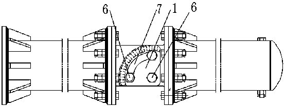
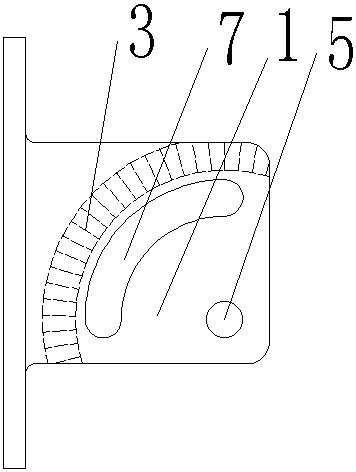
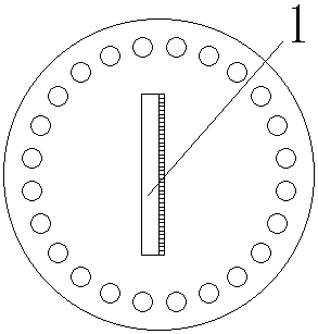
[0017] Such as figure 1 , figure 2 , image 3 , Figure 4 , Figure 5 , Image 6 As shown, the rotation adjustment device of the steel pipe frame jumper in the present invention includes: a first adjustment plate 1 and a second adjustment plate 2; grooves 3 arranged at intervals in a fan ring are arranged on a plane on one side of the first adjustment plate , the side plane of the second adjusting plate is provided with the convex teeth 4 arranged at intervals corresponding to the fan-shaped annular groove 3 on the first adjusting plate; the first adjusting plate has the groove 3 The surface and the surface of the second adjusting plate having the convex teeth 4 ...


PUM


Abstract

A rotation adjusting device for a steel pipe skeleton jumper comprises a first adjusting plate and a second adjusting plate. Fan-shaped grooves are arranged on the surface of a side of the first adjusting plate at intervals. Fan-shaped protrusions are arranged on the surface of a side of the second adjusting plate and correspondingly match the fan-shaped grooves on the first adjusting plate. The surface having the grooves of the first adjusting plate and the surface having the protrusions of the second adjusting plate are attached to each other and are fixedly connected to each other by a fastener. The rotation adjusting device for the steel pipe skeleton jumper according to the claim 1 is characterized in that the first adjusting plate and the second adjusting plate are provided with fastening bolt holes at the circle centers of the fan shapes of the grooves and the protrusions respectively; the two adjusting plates are fixedly connected by a bolt. The rotation adjusting device for asteel pipe skeleton jumper according to the claim 1 is characterized in that the first adjusting plate and the second adjusting plate are provided with corresponding fan ring holes, and the fasteningbolt pass through the fan ring holes to fix the two adjusting plates, and the circle centers of the fan ring holes coincide with the circle centers of the fan shapes of the grooves and the protrusions. The rotation adjusting device for a steel pipe skeleton jumper according to the claim 1 is characterized in that the grooves or the protrusions have an interval angle of 0.50 to 30 degrees.

Description

technical field [0001] The invention relates to a rotation adjusting device for a steel pipe frame jumper, which belongs to the technical field of electric power fittings. Background technique [0002] Skeleton jumpers are often used as the main connection method of tension tower jumpers in UHV transmission lines. Skeleton jumpers not only play a supporting role in the jumper, but also can reduce the size of the tower head and reduce the project cost. However, the straight steel pipe frame used for the intermediate phase jumper is prone to fatigue fracture and corona in the sharp bend during long-term operation. In this field, the intermediate phase jumper usually adopts the method of installing curved steel pipe joints at the end of the frame to solve this problem, but The angle and direction of the exit bend of the bobbin jumper is difficult to determine. The notification number is CN204089068U Rotation adjustment device for skeleton jumper. An adjustment plate is designe...

Claims


Application Information

Patent Timeline
Patent Type & Authority Applications(China)
IPC IPC(8): H02G7/20
CPCH02G7/20
Inventor 朱玉鹏乔庆文陈进黄国柱李良
Owner 中国电建集团河南电力器材有限公司
Why Eureka
Try Eureka