
Method and device system for exploiting natural gas by utilizing ocean surface layer warm water
A natural gas and warm water technology, applied in the field of energy exploitation, can solve problems such as the inability to exploit combustible ice
- Summary
- Abstract
- Description
- Claims
- Application Information
AI Technical Summary
Problems solved by technology
Method used
Image

Examples
Embodiment Construction
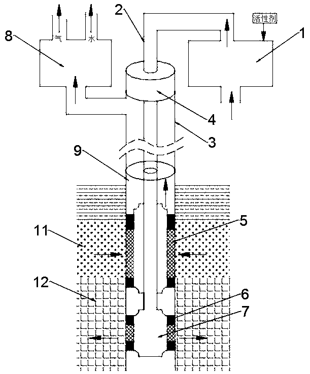
[0037] The present invention will be further explained below in conjunction with the accompanying drawings. These drawings are all simplified schematic diagrams, which only illustrate the basic structure of the present invention in a schematic manner, so they only show the configurations related to the present invention.
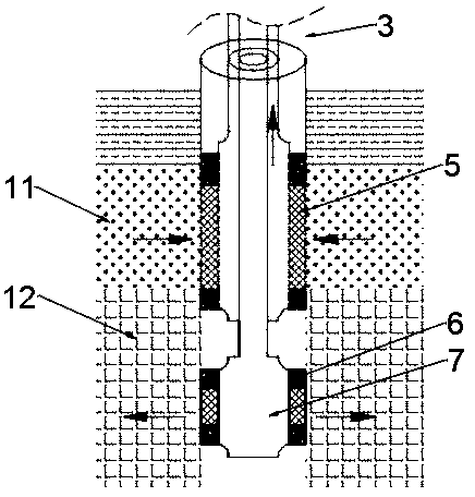
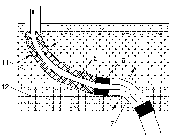
[0038] The structure of Embodiment 1 of the present invention is as follows figure 1 As shown, the mining device of this embodiment includes a warm water control system 1 for inhaling heated and pressurized ocean surface water, a warm water pipe 2, a casing 3, a downhole control device 7 and a separation and lifting system 8. The warm water pipe 2, The downhole control device 7, the sand control screen 5 and the packer 6 are all placed in the casing 3 and enter the downhole. The end of the warm water pipe 2 is connected with the downhole control device 7 to inject warm water into the pore reservoir (12). The outer wall of the downhole control device 7 and ...
PUM
 Abstract
Description
Claims
Application Information