
Display screen device and mobile terminal

A technology of mobile terminals and display screens, applied in projection devices, identification devices, printing devices, etc., can solve the problems of being unable to move, affecting the effect of taking photos, and not being able to intuitively select the best photos, etc., to achieve high practical value, Selfie natural effect

Pending Publication Date: 2018-10-19
GREE ELECTRIC APPLIANCES INC
View PDF5 Cites 10 Cited by
  • Summary
  • Abstract
  • Description
  • Claims
  • Application Information

AI Technical Summary

Problems solved by technology

[0003] When mobile terminal electronic products such as smartphones and PADs (tablet computers) take pictures, especially when taking selfies, they all take pictures through the front camera, but the position of the front camera of the existing mobile terminal electronic products is generally fixed on the mobile terminal. the head or the bottom, and does not move
When people are taking selfies, their eyes must look directly at the front camera lens to make the photos they take are frontal. In this way, they cannot always see the real-time effects of selfies on the screen of the mobile phone, and cannot intuitively choose the best photos; If the human eyes stare directly at the selfie photo displayed on the screen, the photo taken at this time is not a frontal photo, and the human eye is squinting, which seriously affects the photo effect
[0004] Moreover, the use of full screens on mobile terminals has become a popular trend. Full screens can increase the screen-to-body ratio of mobile terminals and achieve a large field of view on a limited screen. However, mobile terminals with shooting functions are all on mobile terminals Holes are opened on the surface of the head or bottom cover, and the traditional camera is installed in the hole to achieve shooting. The position of the front camera and the hole restricts the design of the full screen, which always leaves a large or small "forehead", which is very difficult. Affects the maximization of the full screen

Method used


Image

  • Display screen device and mobile terminal
  • Display screen device and mobile terminal

Examples


Embodiment Construction

[0029] In order to make the purpose, technical solution and advantages of the present invention clearer, the technical solution of the present invention will be described in detail below. Apparently, the described embodiments are only some of the embodiments of the present invention, but not all of them. Based on the embodiments of the present invention, all other implementations obtained by persons of ordinary skill in the art without making creative efforts fall within the protection scope of the present invention.

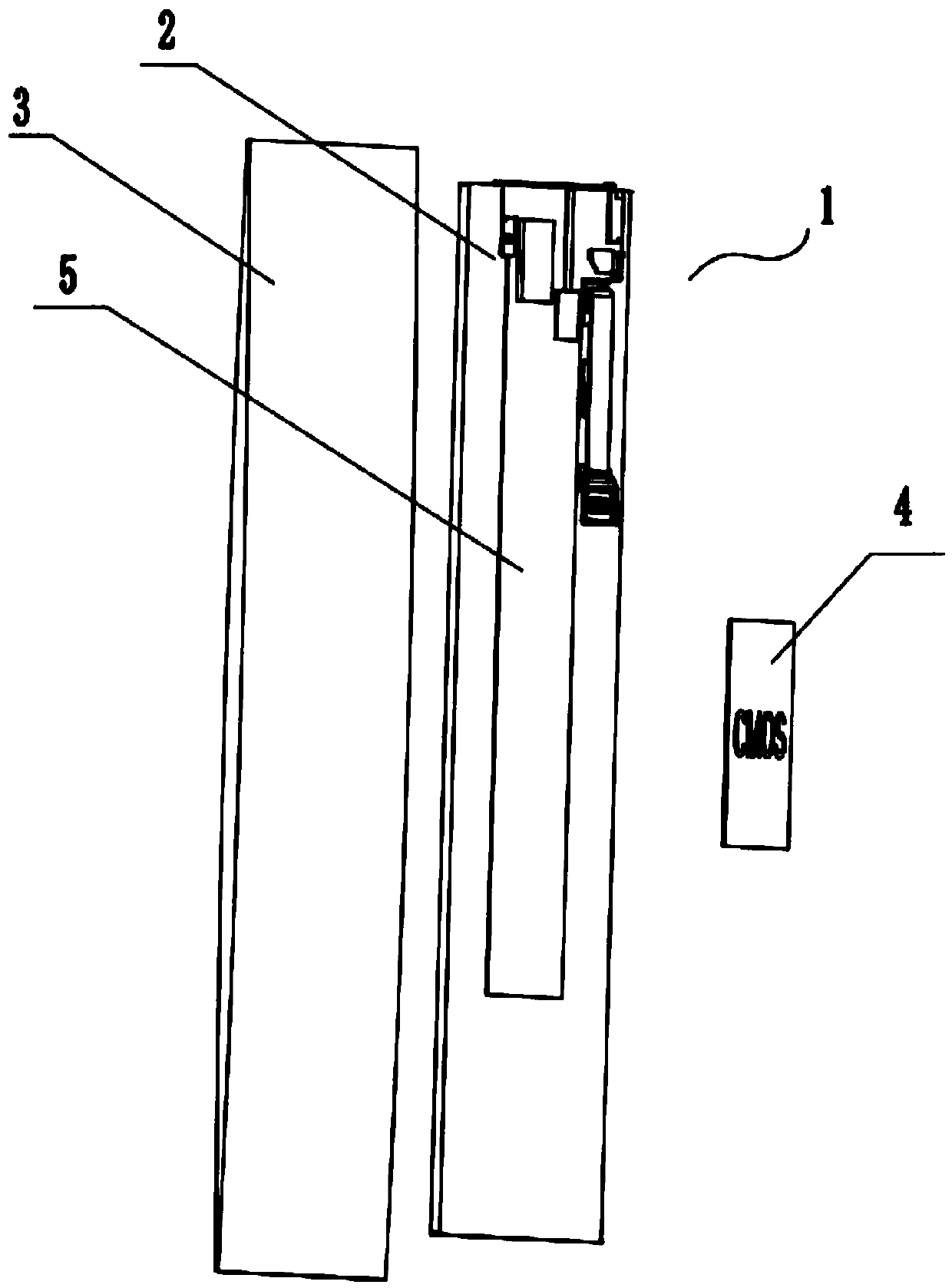
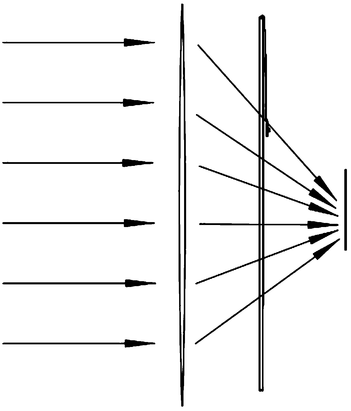
[0030] The invention provides a display device such as Figure 1-Figure 2 As shown, the display screen device includes: a display module 1, a light-transmitting cover plate 3 and an image sensor 4, wherein the display module 1 includes a light-transmitting display panel 2; the light-transmitting cover plate 3 covers the front of the display panel 2 On the side, the image sensor 4 is arranged on the back side of the display panel 2 and is used to collect light i...


PUM


Abstract

The invention provides a display screen device, and relates to the technical field of image display devices. The display screen device comprises a display module, the display module comprises a photopermeability display panel, a photopermeability cover plate covering the front side of the display panel and an image sensor, wherein at least one of the display panel and the photopermeability cover plate is a lens structure which can gather incident light; the image sensor is arranged at the back side of the display panel and used for collecting information of the light gathered by the lens structure. The invention further provides a mobile terminal comprising the above display screen device. The mobile terminal is simple in structure, the display panel or photopermeability cover plate is arranged as the lens structure which can gather light, the arrangement of 'a part in a forehead shape' of the mobile terminal is cancelled, full screen is really achieved, and a user can visually shoot in real time, so that the selfie taking effect is more natural.

Description

technical field [0001] The present invention relates to the technical field of image display devices, in particular to a display screen device and a mobile terminal. Background technique [0002] Mobile terminal electronic products such as smartphones and PADs (tablet computers) have been widely used in people's daily life. Mobile terminal electronic products can watch news, watch performances and have shooting functions, and are loved by people. [0003] When mobile terminal electronic products such as smartphones and PADs (tablet computers) take pictures, especially when taking selfies, they all take pictures through the front camera, but the position of the front camera of the existing mobile terminal electronic products is generally fixed on the mobile terminal. The head or the bottom, and cannot move. When people are taking selfies, their eyes must look directly at the front camera lens to make the photos they take are frontal. In this way, they cannot always see the r...

Claims


Application Information

Patent Timeline
Patent Type & Authority Applications(China)
IPC IPC(8): G09F9/00G09F9/35G03B29/00
CPCG03B29/00G09F9/00G09F9/35
Inventor 郑亚东许超谢明龙世才
Owner GREE ELECTRIC APPLIANCES INC
Learn More