Alternating current/direct current charging control guiding circuit of electric vehicle conduction charging system and control method of circuit

A technology of AC and DC charging, control and guidance, applied in the direction of electric vehicle charging technology, electric vehicles, battery circuit devices, etc., can solve the problems of inability to save high-reliability power-down data, poor compatibility, and high system standby power consumption

CN108819786AActive Publication Date: 2018-11-16ZHENGZHOU UNIVERSITY OF LIGHT INDUSTRY
5 Cites 12 Cited by

Patent Information

Authority / Receiving Office
CN · China
Patent Type
Applications(China)
Current Assignee / Owner
Publication Date
2018-11-16

Smart Images

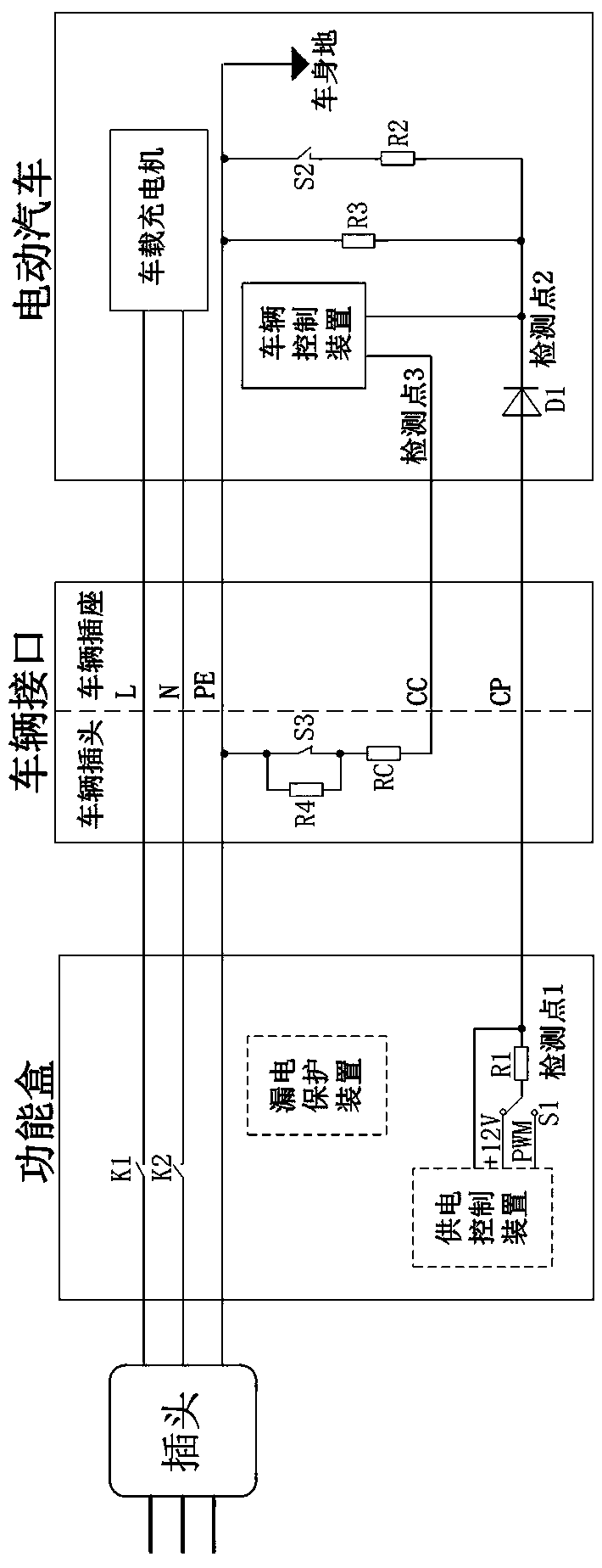
  • Figure 1
    Figure 1
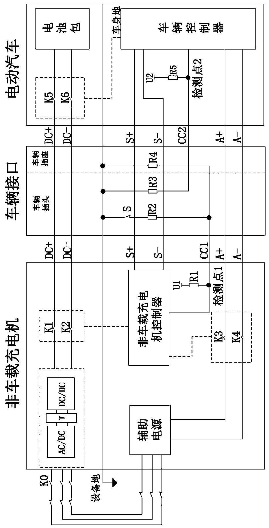
  • Figure 2
    Figure 2
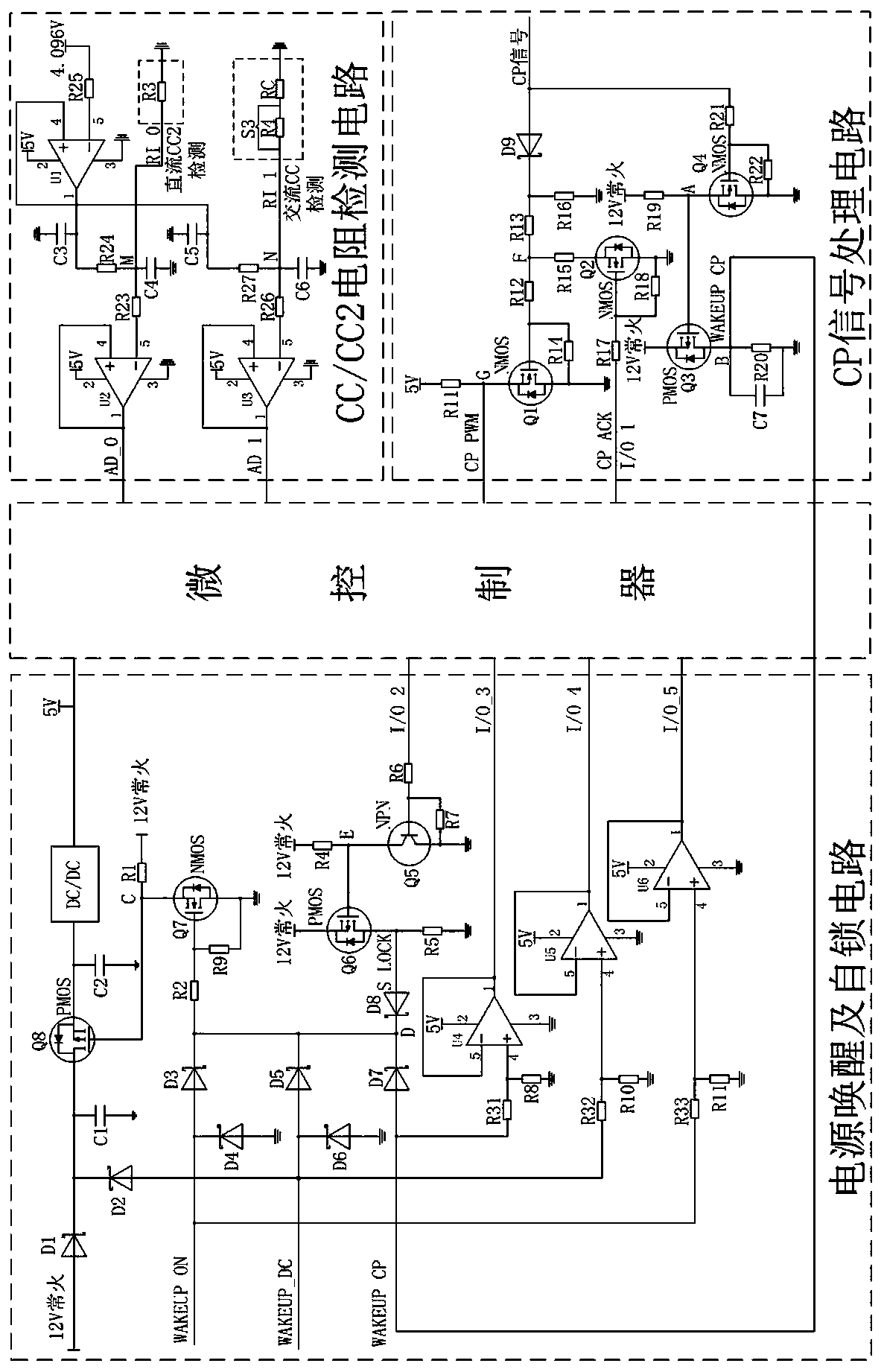
  • Figure 3
    Figure 3
Patent Text Reader

Abstract

The invention discloses an alternating current / direct current charging control guiding circuit of an electric vehicle conduction charging system and a control method of the circuit. The alternating current / direct current charging control guiding circuit includes four parts including a power source waking and self-locking circuit, a CC / CC2 resistance detection circuit, a CP signal processing circuit and a microcontroller. The alternating current / direct current charging control guiding circuit has the advantages that the stand-by power consumption is low, delayed power failure can be achieved, an alternating current / direct current charging control guidance mode and a normal vehicle running guidance mode are both compatible, there are no mechanical contact points, and the service life is long. The provided alternating current / direct current charging control guiding circuit of the conduction charging system is usually integrated in a battery management system or a vehicle control unit. Switch devices adopted in the design are all MOS components, mechanical losses are avoided, the service life of a switch is prolonged, and the reliability of the alternating current / direct current charging control guiding circuit is improved.
Need to check novelty before this filing date? Find Prior Art

Description

technical field

[0001] The invention belongs to the field of electric vehicles, and in particular relates to an AC / DC charging control guide circuit and a control method for a conduction charging system of an electric vehicle. Background technique

[0002] Energy shortage and environmental pollution are serious challenges to my country's sustainable economic development, and it is imperative to develop green transportation. "Pure electric drive" is the strategic orientation of my country's automobile industry. How to ensure the safe and reliable connection between electric vehicles and charging equipment is one of the basic functional requirements of electric vehicles. Therefore, the design of a charger interface guide circuit that meets the requirements of the national standard and is compatible with the AC charging mode and the DC charging mode is an important guarantee for the safe and reliable driving of the vehicle.

[0003] The purpose of AC and DC charging control gu...

Examples

Embodiment Construction

[0050] Below in conjunction with accompanying drawing and embodiment the present invention will be further described:

[0051] Such as image 3 As shown, the invented conductive charging system AC and DC charging control guide circuit is composed of four parts: power wake-up and self-lock circuit, CC / CC2 resistance detection circuit, CP signal processing circuit and microcontroller; power wake-up and self-lock circuit through The 5V power supply, I / O_2, I / O_3, I / O_4, and I / O_5 signals are connected to the general-purpose input and output ports of the microcontroller, and are connected to the CP signal processing circuit through the "WAKEUP_CP" signal; the CC / CC2 resistance detection circuit is connected through the " The AD_0" signal and "AD_1" signal are connected to the analog signal acquisition port of the microcontroller; the CP signal processing circuit is connected to the PWM detection port of the microcontroller through the "CP_PWM" signal, and connected to the general ...