

Motor having circuit for decreasing standby current
A technology of electric motors and circuits, applied in the field of electric motors, can solve the problems of large-scale and complicated current cut-off circuits, and achieve the effect of compact and simple structure and miniaturization
- Summary
- Abstract
- Description
- Claims
- Application Information
AI Technical Summary
Problems solved by technology
Method used
Image

Examples
Embodiment approach 1
[0029] (the whole frame)
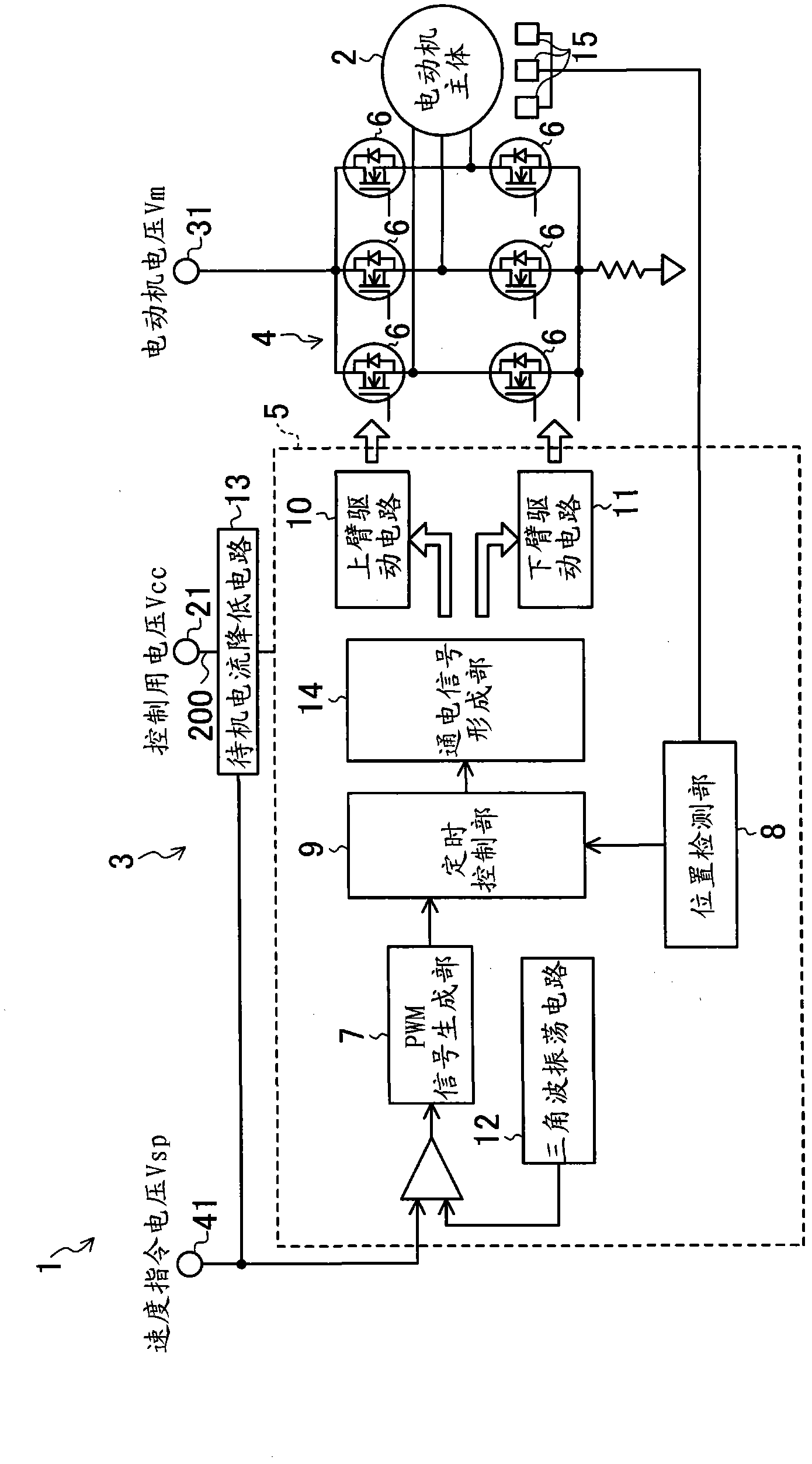
[0030] figure 1 A motor according to an embodiment of the present invention is shown. This motor 1 is a so-called brushless DC motor (hereinafter simply referred to as a motor) 1 and has a motor body 2 and a drive circuit 3 for driving the motor body 2 .
[0031] The motor main body 2 has a rotor, three-phase stator coils, and a substantially cylindrical motor case (not shown) that covers components such as the stator.
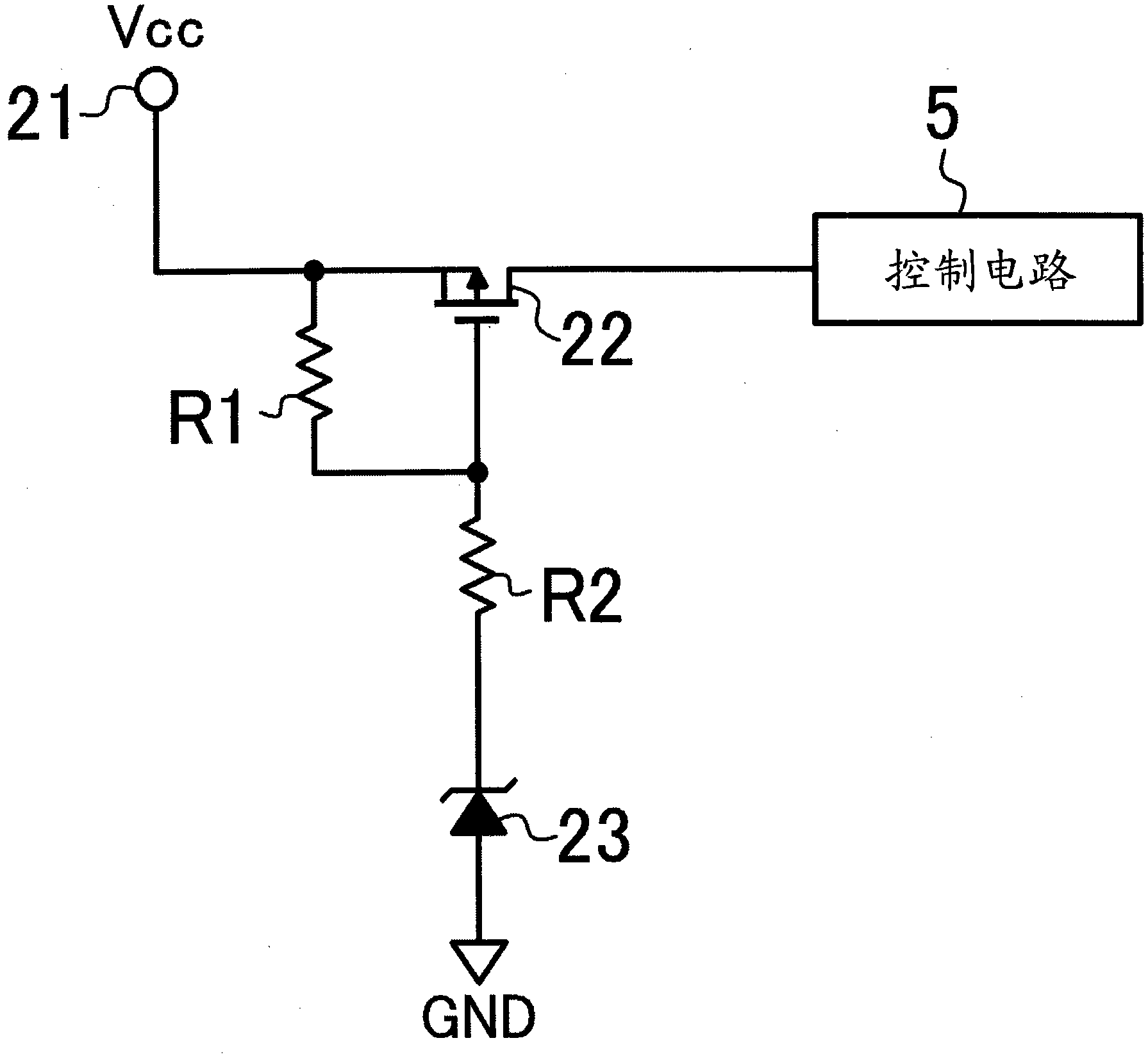
[0032] The drive circuit 3 described above is mounted on a substrate arranged in the motor case. The drive circuit 3 includes an inverter circuit 4 for supplying drive current to stator coils of each phase of the motor body 2 , a control circuit 5 for controlling the inverter circuit 4 , and a standby current reduction circuit 13 described later.
[0033] The inverter circuit 4 is composed of six switching elements 6 , and the driving timing of each switching element 6 is switched based on a control signal output from the control ...
Embodiment approach 2
[0061] Figure 5 The standby current reduction circuit 13 of Embodiment 2 is shown. The standby current reduction circuit 13 of the second embodiment is configured to block the current supply path between the control power supply and the control circuit 5 according to the voltage value of the motor voltage Vm.
[0062] That is, an additional circuit 60 including a Vm input terminal 31 for inputting a motor voltage Vm and a comparator 26 is connected to the gate terminal of the MOS transistor 22 .
[0063] The comparator 26 is connected to the gate terminal of the MOS transistor 22 via the resistor R2. The non-inverting input terminal of the comparator 26 is connected to a point b1 on the current path spanning between the Vcc input terminal 21 and the ground. On this current path, resistors R3 and R4 are arranged in series across a point b1. The inverting input terminal of the comparator 26 is connected to a point b2 on the current path spanning between the Vm input terminal...
Embodiment approach 3
[0069] Figure 6 The configuration of standby current reduction circuit 13 according to Embodiment 3 of the present invention is shown. The standby current reduction circuit 13 of the third embodiment is configured to block the current supply path between the control power supply and the control circuit 5 based on the control voltage Vcc and the speed command voltage Vsp.
[0070] Specifically, the standby current reduction circuit 13 has a main circuit 50 to which a control voltage Vcc is input, and an additional circuit 60 to which a speed command voltage Vsp is input.
[0071] The configuration of the main circuit 50 is the same as that of the standby current reduction circuit 13 in Embodiment 1 described above, and therefore description thereof will be omitted here.
[0072] The additional circuit 60 has a Vsp input terminal 41 to which a speed command voltage Vsp is input, and an N-channel MOS transistor 27 that blocks a current path between the MOS transistor 22 and the...
PUM
 Abstract
Description
Claims
Application Information