Switching type voltage stabilizer control circuit and method for stably outputting electric signals

A control circuit and control signal technology, applied in the output power conversion device, the conversion of DC power input to DC power output, electrical components, etc. Effect of Standby Current

Active Publication Date: 2016-02-03
PHISON ELECTRONICS
View PDF5 Cites 3 Cited by
  • Summary
  • Abstract
  • Description
  • Claims
  • Application Information

AI Technical Summary

Problems solved by technology

Therefore, if the power supply of this system is the application of batteries or portable electronic products, it cannot meet the requirements of low current consumption and extended battery life in the market

Method used


Image

  • Switching type voltage stabilizer control circuit and method for stably outputting electric signals
  • Switching type voltage stabilizer control circuit and method for stably outputting electric signals
  • Switching type voltage stabilizer control circuit and method for stably outputting electric signals

Examples


Embodiment Construction

[0092] Reference will now be made in detail to the exemplary embodiments of the present invention, examples of which are illustrated in the accompanying drawings. In addition, wherever possible, elements / components / symbols with the same reference numerals are used in the drawings and embodiments to represent the same or similar parts.

[0093] Several exemplary embodiments are proposed below to illustrate the present invention, but the present invention is not limited to the illustrated exemplary embodiments. And appropriate combinations are also allowed among exemplary embodiments. The term "coupling" used throughout the specification of this case (including the scope of claims) may refer to any direct or indirect means of connection. For example, if it is described that a first device is coupled to a second device, it should be interpreted as that the first device can be directly electrically connected to the second device, or that the first device can be electrically conne...


PUM


Abstract

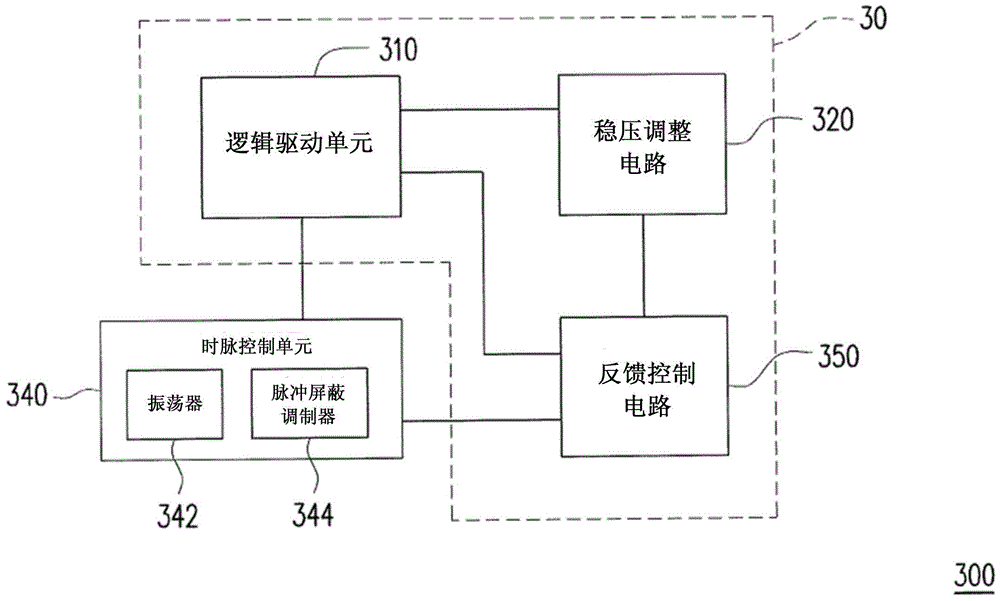
The invention provides a switching type voltage stabilizer control circuit and a method for stably outputting electric signals. The switching type voltage stabilizer control circuit comprises a switching type voltage stabilizer and a clock control unit; the switching type voltage stabilizer regulates the output voltage according to reference voltage and feedback voltage; the clock control unit is coupled with the switching type voltage stabilizer, and the clock control unit comprises an oscillator and a pulse shielding modulator; the oscillator is for providing an oscillating signal; the pulse shielding modulator is for generating a control signal for shielding a part of the oscillating signal; and the clock control unit is for providing a control signal for maintaining the output electric signal of the switching type voltage stabilizer in a sleep mode to be within a predetermined section.

Description

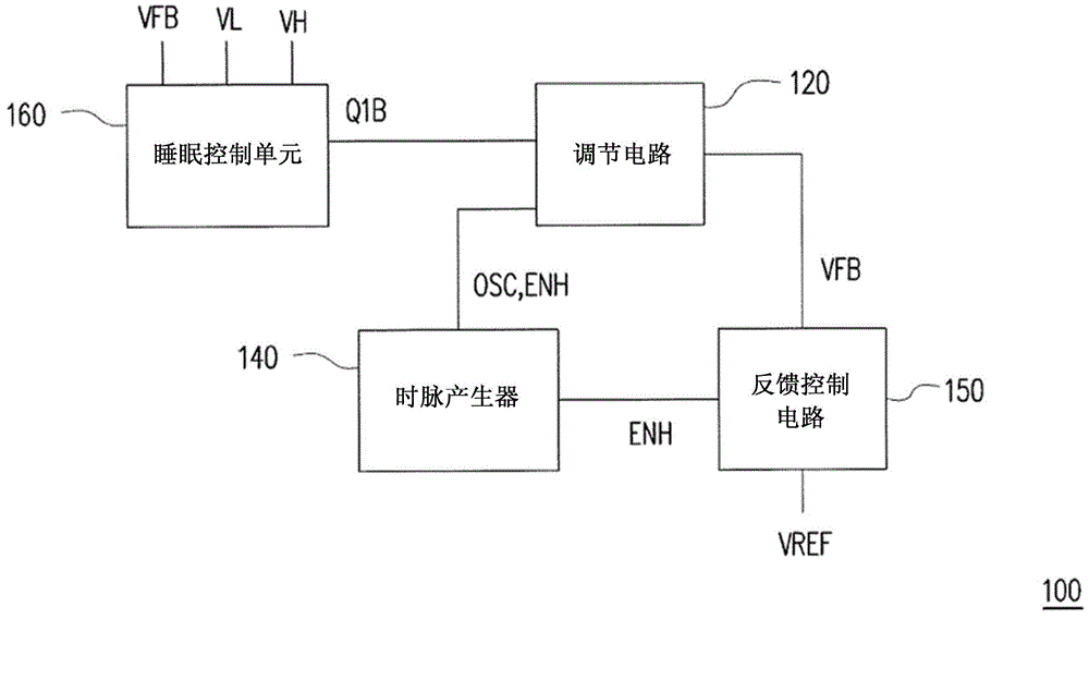
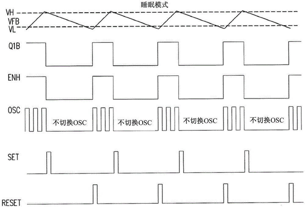
technical field [0001] The present invention relates to a control circuit of a switching voltage regulator and a method for stabilizing an electrical signal output, and in particular to a switching voltage regulator with ultra-low current consumption in sleep mode. A voltage regulator control circuit and a method for stably outputting electrical signals. Background technique [0002] Existing circuit systems often require a voltage regulator to provide an accurate output voltage as a reference for other circuit operations. There are many switching regulators that generate a reference voltage by themselves, and then use an error amplifier (erroramplifier) ​​and a feedback mechanism to regulate the above-mentioned output voltage. [0003] figure 1 is a schematic block diagram of a switching regulator shown according to the prior art. Please refer to figure 1 , the switching regulator 100 includes a regulation circuit 120 , a clock generator 140 , a feedback control circuit...

Claims


Application Information

Patent Timeline
Patent Type & Authority Applications(China)
IPC IPC(8): H02M3/156
Inventor 张正晖郑文隆
Owner PHISON ELECTRONICS
Why Eureka
Try Eureka