Tail removal machine for spiral shells

A technology of tail machine and snail, which is applied in the field of snail tail cutting machine, and can solve the problem that the tail of snail cannot be guaranteed to be completely removed.

Inactive Publication Date: 2018-11-27
黎杰
View PDF1 Cites 6 Cited by
  • Summary
  • Abstract
  • Description
  • Claims
  • Application Information

AI Technical Summary

Problems solved by technology

[0002] In China, many places like to eat snails. At present, the tails of snails are basically cut off by hand. The prior art snail tail removal machine is such as: patent CN106615015A. The disadvantage of the sn

Method used


Image

  • Tail removal machine for spiral shells
  • Tail removal machine for spiral shells
  • Tail removal machine for spiral shells

Examples


Embodiment Construction

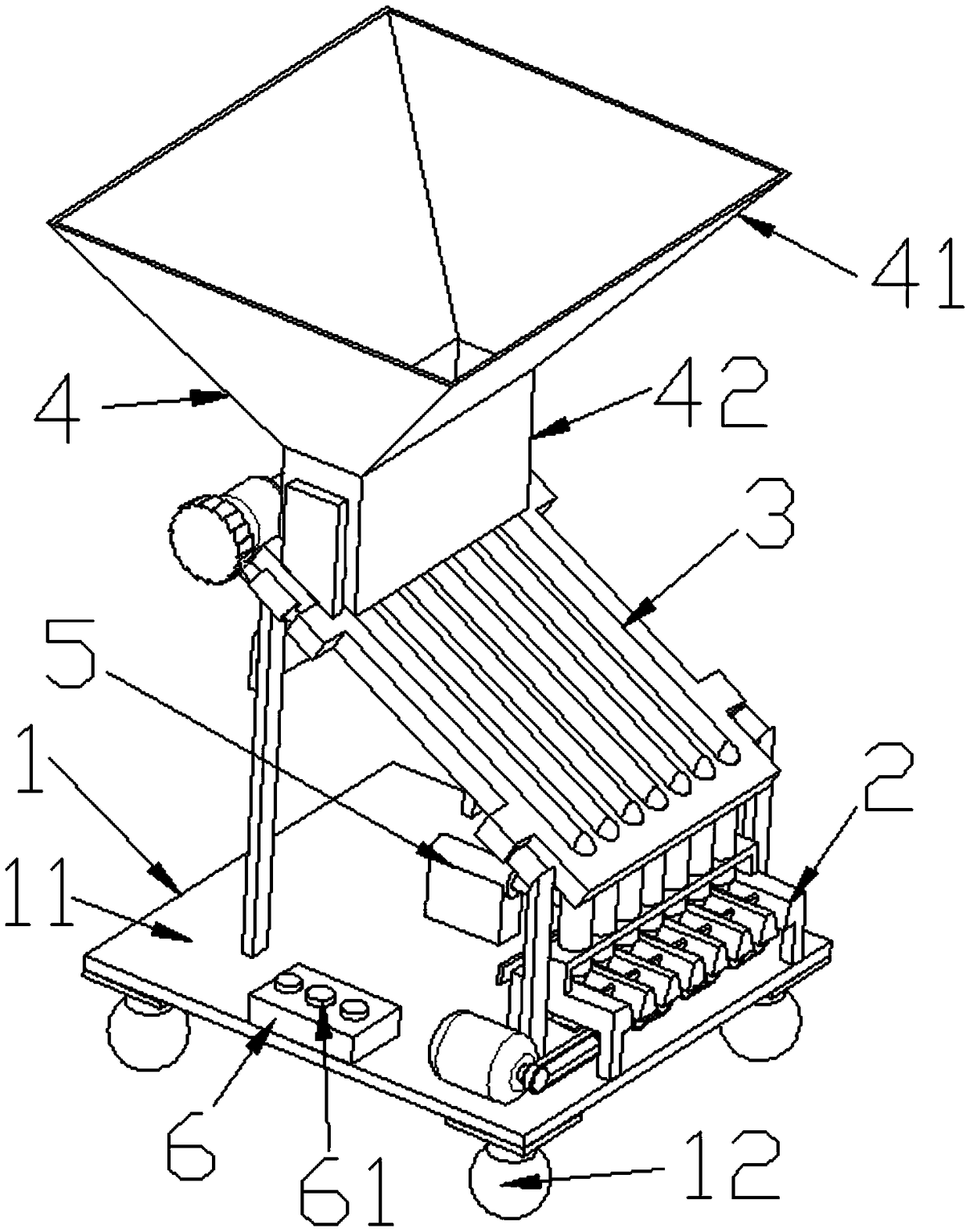
[0036] Such as Figure 1 to Figure 9 As shown, a snail tail removal machine is characterized in that it includes a base part 1, a tail removal part 2, a screening part 3, a funnel part 4, a pushing mechanism 5, and a control device 6;

[0037] The base part 1 includes a base plate 11;

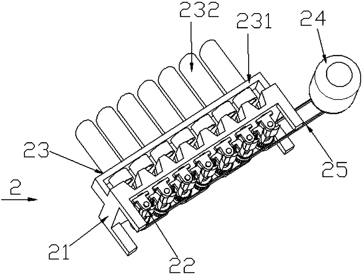
[0038] The tail removal part 2 includes a tail removal platform 21, a tail removal knife assembly 22, a feeding tube assembly 23, and a drive motor 24;

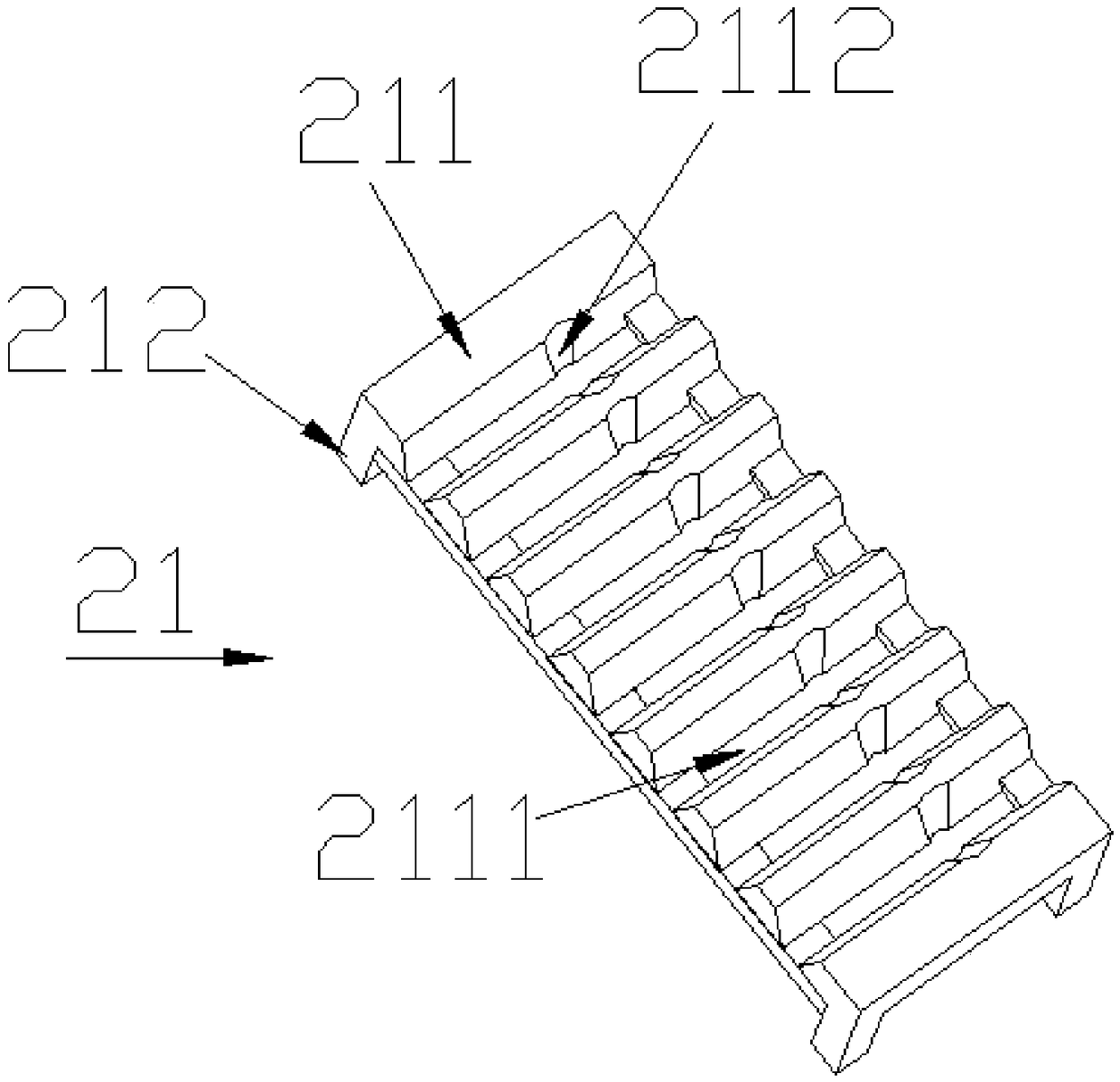
[0039] The tail-removing platform 21 includes a placement plate 211, the placement plate 211 is horizontally provided with a plurality of first trapezoidal grooves 2111, the first trapezoidal grooves 2111 are provided with conical grooves 2112, and support legs are provided below the placement plate 211 212; the supporting legs 212 are fixed above the base plate 11;

[0040] The feeding tube assembly 23 includes a feeding tube 231, and the feeding tube 231 is vertically arranged directly above the conical groove portion 2112, and a feeding t...


PUM


Abstract

The invention relates to a tail removal machine for spiral shells. The machine is characterized by comprising a base part, a tail removal part, a screening part, a funnel part, a pushing mechanism anda control device. The screening part comprises an inclining plate, front supporting legs, rear supporting legs and rotation wheels. According to the tail removal machine, the tails of the spiral shells can be automatically removed, and it is guaranteed that the tails of all the spiral shells are removed.

Description

Technical field: [0001] The invention relates to a snail tail cutting machine. Background technique: [0002] In China, many places like to eat snails. At present, the tails of snails are basically cut off by hand. The prior art snail tail removal machine is such as: patent CN106615015A. The disadvantage of the snail tail is that the device has a certain randomness and cannot guarantee to completely remove all the snail tails. After each use, there are always some snails whose tails have not been removed mixed in the middle. Invention content: [0003] The purpose of the present invention is to provide a snail tail cutting machine aimed at the deficiencies of the prior art, which can not only automatically remove the snail tail, but also ensure that each snail tail is removed. [0004] Technical solutions of the present invention are as follows: [0005] A snail tail removal machine, characterized in that it includes a base part, a tail removal part, a screening part, a ...

Claims


Application Information

Patent Timeline
IPC IPC(8): A22C29/00
CPCA22C29/024
Inventor 黎杰
Owner 黎杰
Why Eureka
Try Eureka