Optical filter mirror plane defect detection method and device and terminal device

A defect detection and filter technology, which is applied in the field of image processing, can solve the problems of low detection accuracy and efficiency of mirror defects, and achieve the effect of improving detection efficiency and detection accuracy and improving overall quality.

Active Publication Date: 2018-11-30
精锐视觉科技(山东)有限公司
View PDF7 Cites 4 Cited by
  • Summary
  • Abstract
  • Description
  • Claims
  • Application Information

AI Technical Summary

Problems solved by technology

[0004] In view of this, an embodiment of the present invention provides a method, device, and terminal equipment for detecting defects on the mi

Method used


Image

  • Optical filter mirror plane defect detection method and device and terminal device
  • Optical filter mirror plane defect detection method and device and terminal device
  • Optical filter mirror plane defect detection method and device and terminal device

Examples


Embodiment 1

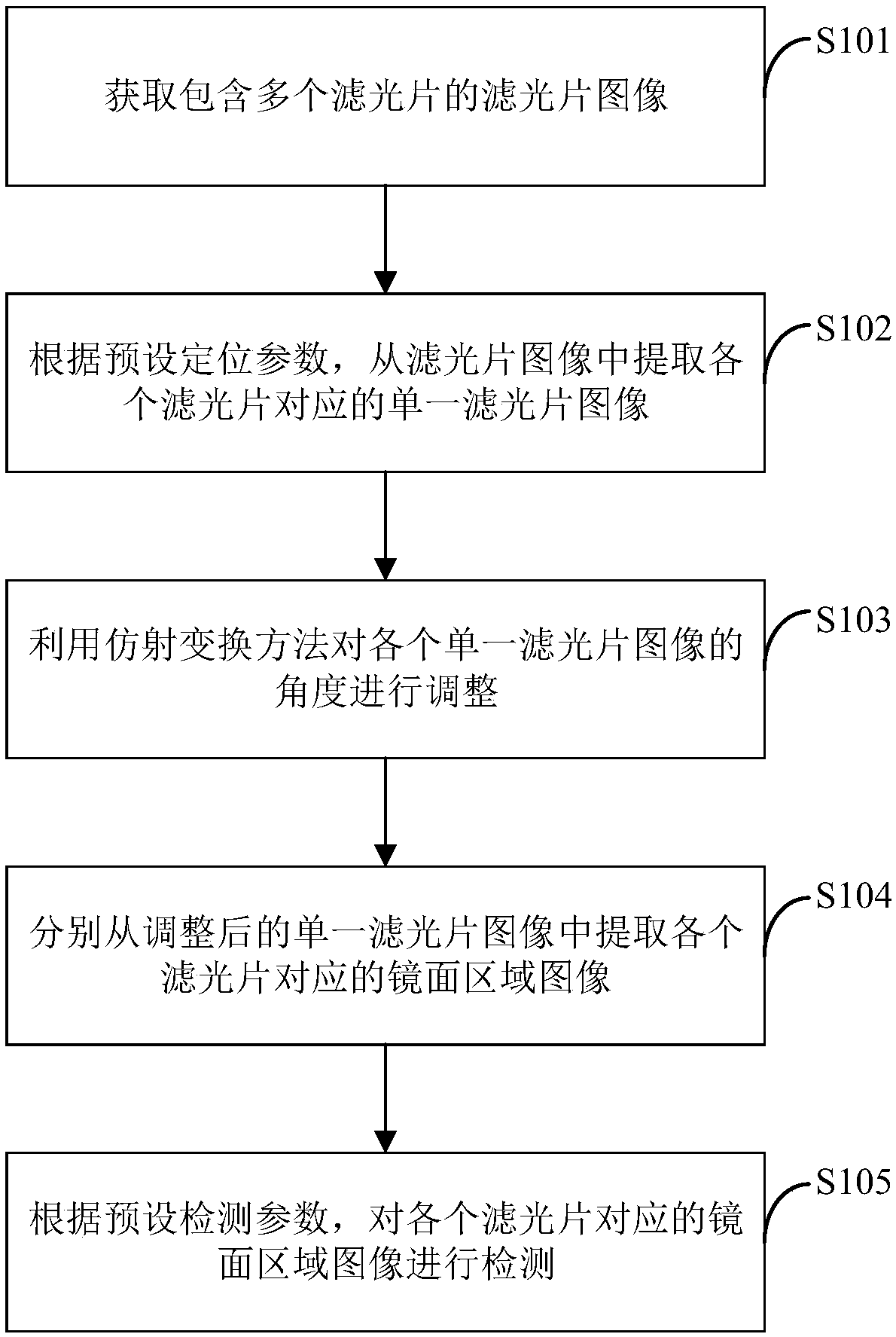
[0034] figure 1 It shows the implementation process of a method for detecting defects on the optical filter mirror surface provided by an embodiment of the present invention. The process execution subject of this embodiment may be a server, and the process is described in detail as follows:

[0035] In S101, a filter image including a plurality of filters is acquired.

[0036] In this embodiment, the filter image includes a plurality of filters, and the plurality of filters are placed on the base, and the images of the filters and the base can be collected by a high-definition camera to obtain the filter image. For example, one filter image can contain 6 filters, so that the mirror surfaces of the six filters can be detected at the same time.

[0037] In this embodiment, when photographing the filter, two different light sources may be used for overhead photographing, including a standard light source and a backlight light source. Among them, the standard light source is a l...

Embodiment 2

[0128] Such as Figure 7 As shown, an optical filter mirror surface defect detection device 100 provided by an embodiment of the present invention is used to perform figure 1 The method step in the corresponding embodiment, it comprises:

[0129] An optical filter image acquisition module 110, configured to acquire an optical filter image comprising a plurality of optical filters;

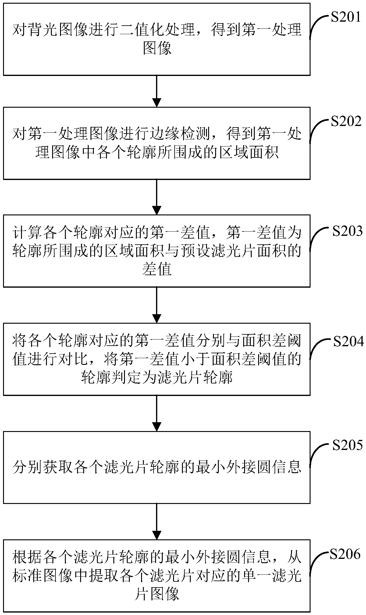
[0130] A single filter image acquisition module 120, configured to extract a single filter image corresponding to each filter from the filter image according to preset positioning parameters;

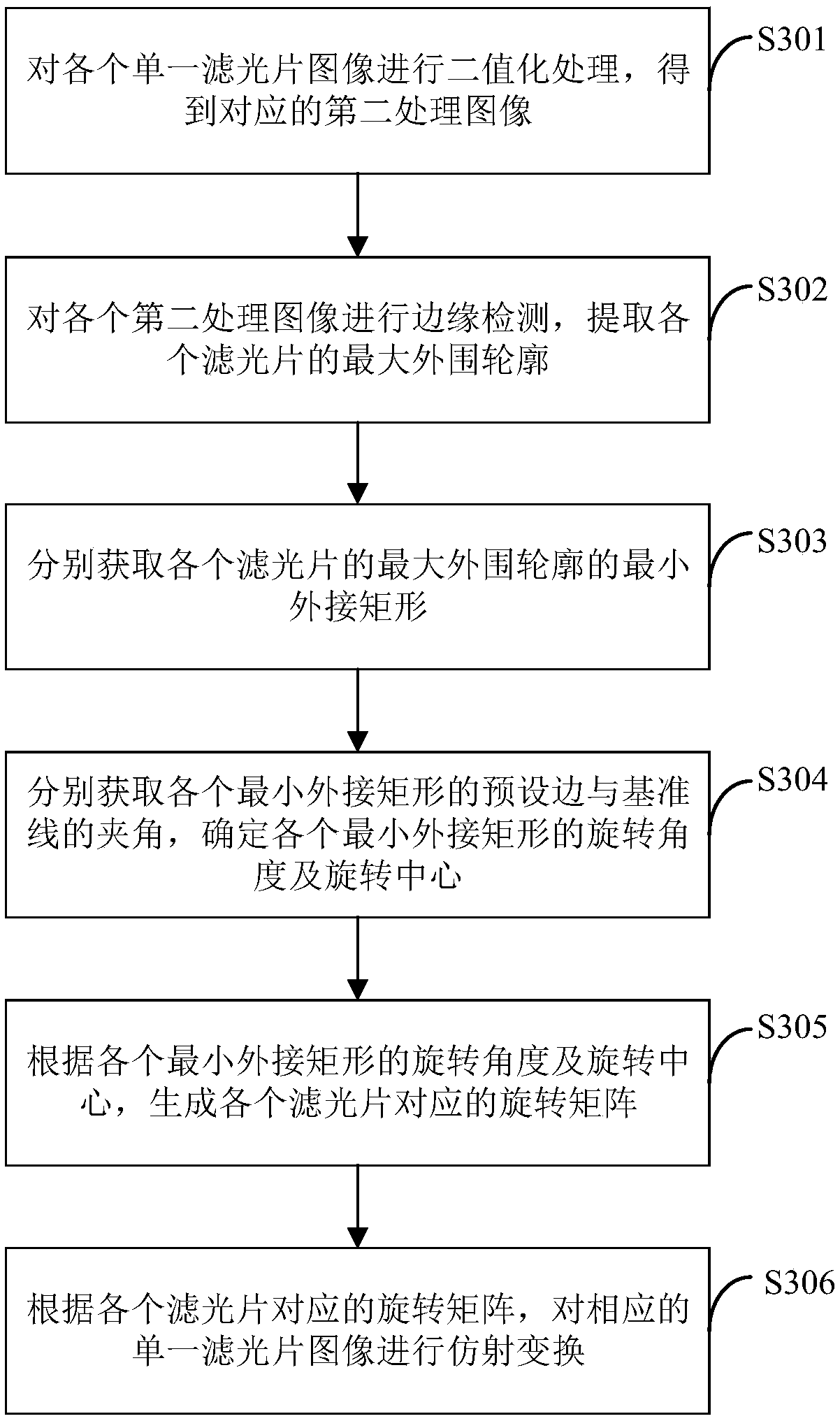
[0131] The angle adjustment module 130 is used to adjust the angle of each single filter image by using an affine transformation method;

[0132] The mirror area image extraction module 140 is used to extract the mirror area images corresponding to each filter from the adjusted single filter image respectively;

[0133] The defect detection module 150 is configured to detect the image of the mirror area c...

Embodiment 3

[0180] The embodiment of the present invention also provides a terminal device 8, including a memory 81, a processor 80, and a computer program 82 stored in the memory 81 and operable on the processor 80. When the processor 80 executes the computer program 82, it realizes Steps in each embodiment as described in embodiment 1, for example figure 1 Step S101 to step S105 are shown. Alternatively, when the processor 80 executes the computer program 82, it realizes the functions of each module in each device embodiment as described in Embodiment 2, for example Figure 7 The functions of modules 110 to 150 are shown.

[0181] The terminal device 8 may be computing devices such as desktop computers, notebooks, palmtop computers, and cloud servers. The terminal device 8 may include, but not limited to, a processor 80 and a memory 81 . For example, the terminal device 8 may also include an input and output device, a network access device, a bus, and the like.

[0182] The so-calle...


PUM


Abstract

The invention is applicable to the technical field of image processing, and provides an optical filter mirror plane defect detection method and device and a terminal device. The optical filter mirrorplane defect detection method comprises the steps that an optical filter image containing a plurality of optical filters is obtained firstly; a single optical filter image corresponding to each optical filter is extracted from the optical filter image according to preset positioning parameters; secondly, the angle of each single optical filter image is adjusted by using an affine transformation method; mirror plane area image corresponding to each optical filter is extracted from the adjusted single optical filter images correspondingly; and finally, according to preset detection parameters, the mirror plane area image corresponding to each optical filter is detected. The optical filter mirror plane defect detection method and device and the terminal device can realize automatic detectionof the mirror planes of the optical filters, improve the detection efficiency and detection accuracy of the optical filter mirror plane defects, and further improve the overall quality of the opticalfilters.

Description

technical field [0001] The invention belongs to the technical field of image processing, and in particular relates to a defect detection method, device and terminal equipment of an optical filter mirror surface. Background technique [0002] As an important part of modern optical devices, optical filters play a key role in improving the functions of optical devices by coating multi-layer films on the surface of base materials and using the interference effect of light, so they are widely used in optical communications. in the network. With the development of remote communication and wavelength division multiplexing technology, optical communication technology puts forward higher requirements on the design and process of optical filters, and the quality of optical filter products becomes particularly important. [0003] In the production process of optical filters, various appearance defects such as scratches, hair, and dirt will inevitably occur. At present, manufacturers u...

Claims


Application Information

Patent Timeline
IPC IPC(8): G01M11/02
CPCG01M11/0207G01M11/0278
Inventor 孔庆杰
Owner 精锐视觉科技(山东)有限公司
Why Eureka
Try Eureka