Laser ultrasonic metal composite plate thickness measuring device and method with light path alignment self-adjusting function

A metal composite plate, laser ultrasonic technology, which is applied to measuring devices, adopts optical devices, and uses ultrasonic/sonic/infrasonic waves, etc., can solve problems such as inability to maintain collinearity, long propagation distance, and difficulty in ensuring that two laser beams are coaxial. Achieve the effect of improving detection accuracy and detection efficiency, and protecting the laser

Active Publication Date: 2022-07-29
TAIYUAN UNIV OF TECH
View PDF22 Cites 0 Cited by
  • Summary
  • Abstract
  • Description
  • Claims
  • Application Information

AI Technical Summary

Problems solved by technology

However, when the excitation and reception of the ultrasonic wave are on opposite sides of the sample, it is difficult to ensure the coaxiality of the two laser beams only by visual observation, resulting in the fact that the ultrasonic excitation point and the receiving point cannot be kept collinear in the thickness direction of the sample. Propagation path greater than sample thickness

Method used


Image

  • Laser ultrasonic metal composite plate thickness measuring device and method with light path alignment self-adjusting function
  • Laser ultrasonic metal composite plate thickness measuring device and method with light path alignment self-adjusting function
  • Laser ultrasonic metal composite plate thickness measuring device and method with light path alignment self-adjusting function

Examples


Embodiment Construction

[0119] In order to further illustrate the technical solutions of the present invention, the present invention will be further described below through examples.

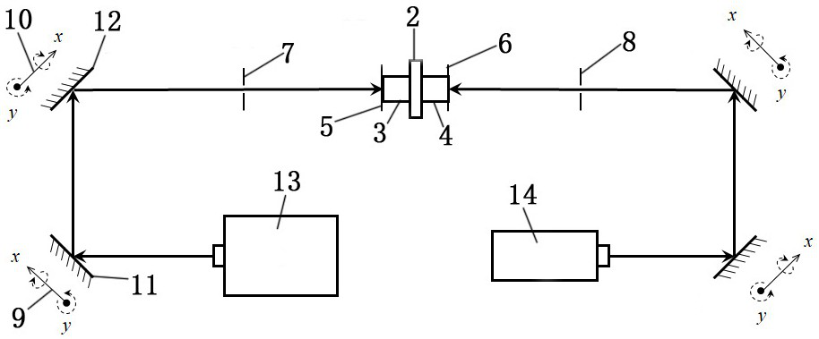
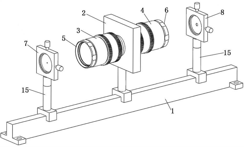
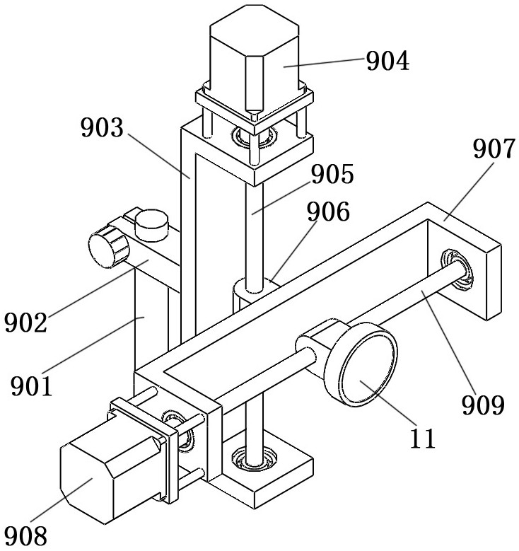
[0120] like Figure 1 to Figure 3 As shown in the figure, the laser ultrasonic metal clad plate thickness measuring device with optical path alignment self-adjustment, including operation platform, slide rail 1, camera coaxial mounting block 2, sample holder, pulsed laser CCD camera 3, continuous laser CCD camera 4, pulsed laser Development screen 5, CW laser development screen 6, pulsed laser aperture 7, CW laser aperture 8, No. 1 angle adjustment mechanism 9, No. 2 angle adjustment mechanism 10, No. 1 mirror 11, No. 2 mirror 12, pulse laser 13 and the optical interferometer 14, the slide rail 1 is installed on the operating platform, the camera coaxial mounting block 2 or the sample holder is installed in the middle of the slide rail 1, and the camera coaxial mounting block 2 is used for alignment of the optical pat...


PUM


Abstract

The invention belongs to the technical field of metal material thickness measurement, and particularly relates to an optical path alignment self-adjusting laser ultrasonic metal composite plate thickness measuring device and method.The optical path alignment self-adjusting laser ultrasonic metal composite plate thickness measuring device is characterized in that a camera coaxial mounting block or a sample clamp is mounted in the middle of a sliding rail; the pulse laser CCD camera and the continuous laser CCD camera are installed on the two sides of the camera coaxial installation block respectively, the pulse laser developing screen and the continuous laser developing screen are installed in front of lenses of the pulse laser CCD camera and the continuous laser CCD camera respectively, and the pulse laser diaphragm and the continuous laser diaphragm are symmetrically installed on the left side and the right side of the sliding rail. Through the combination of the pulse laser CCD camera, the continuous laser CCD camera, the pulse laser diaphragm and the continuous laser diaphragm, it can be guaranteed that two laser beams are adjusted to be coaxial within the error range, and it is avoided that only an excitation point and a detection point are adjusted to be collinear in the thickness direction.

Description

technical field [0001] The invention belongs to the technical field of metal material thickness measurement, and in particular relates to a laser ultrasonic metal composite plate thickness measurement device and method with optical path alignment and self-adjustment. Background technique [0002] Metal composite panels can meet performance requirements that cannot be met by a single metal, give full play to the respective advantages of base materials and clad materials, and achieve optimal performance configuration between materials. The thickness of the base material and the cladding material of the metal clad plate has an important influence on the key properties such as the strength and conductivity of the clad plate. Therefore, the accurate thickness measurement of the base material and the clad material plays an important role in the evaluation of the service performance of the clad plate. [0003] Commonly used metal clad plate thickness measurement methods include mag...

Claims


Application Information

Patent Timeline
IPC IPC(8): G01B17/02G01B11/06
CPCG01B17/02G01B11/06
Inventor 张彦杰王涛闫鹏弓鹏飞和东平张金柱张炜于程豪张超张勇
Owner TAIYUAN UNIV OF TECH
Why Eureka
Try Eureka