Rotating throwing device and multi-angle throwing method

A technology of rotating rods and mounting plates, applied in the direction of sports accessories, etc., can solve problems such as lack, and achieve the effect of high speed

Pending Publication Date: 2018-12-18
SOUTH CHINA UNIV OF TECH
View PDF6 Cites 2 Cited by
  • Summary
  • Abstract
  • Description
  • Claims
  • Application Information

AI Technical Summary

Problems solved by technology

Such a type of robot needs a multi-angle projectile device. At present, the rese

Method used


Image

  • Rotating throwing device and multi-angle throwing method
  • Rotating throwing device and multi-angle throwing method
  • Rotating throwing device and multi-angle throwing method

Examples


Embodiment 1

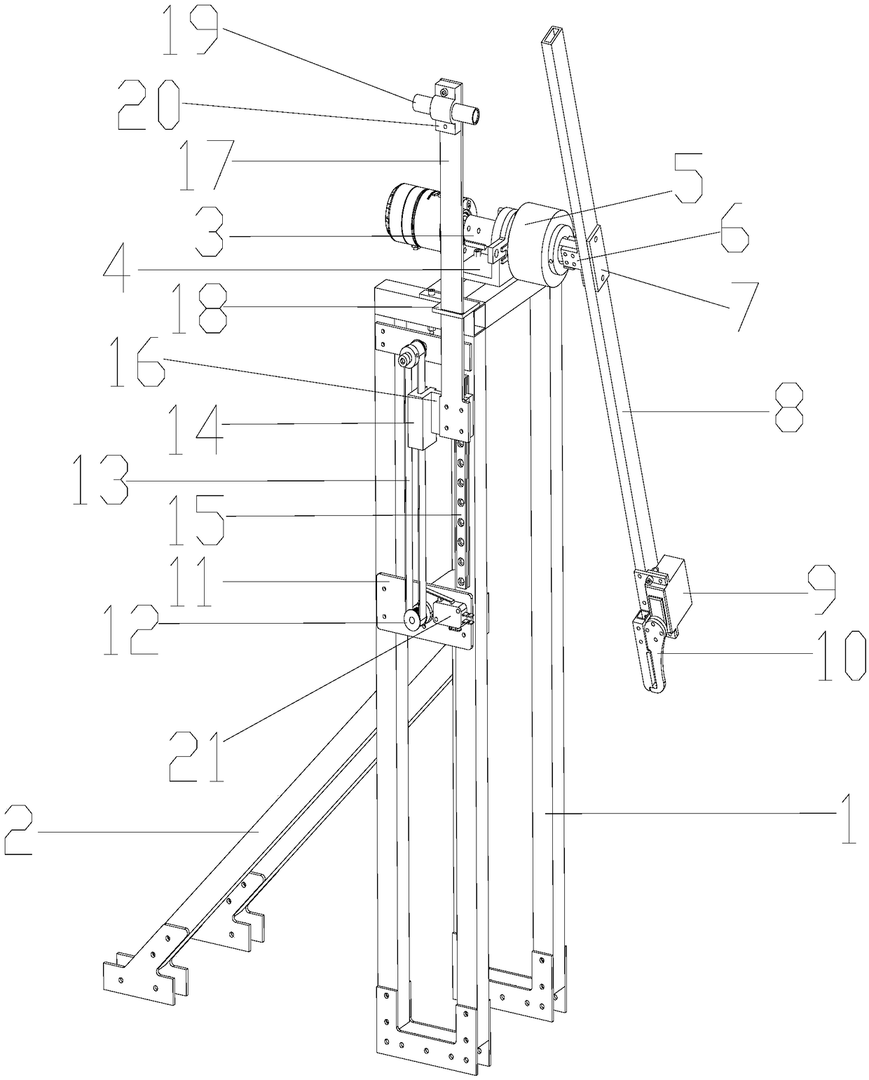
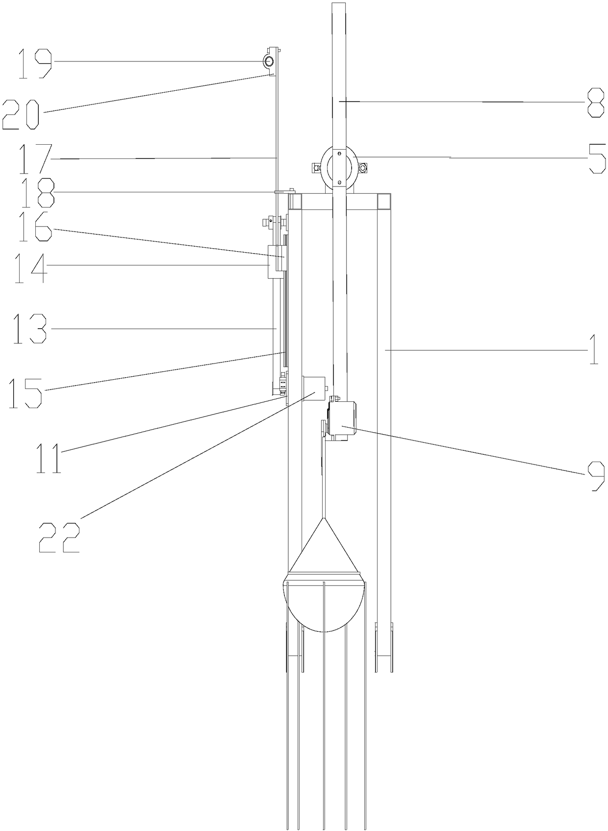
[0031] like figure 1 and figure 2 As shown, a rotating projectile device in this embodiment includes a frame 1, a drive motor 3, a motor base 4, a conductive slip ring 5, a connecting corner code 6, a connecting block 7, a rotating rod 8, a steering gear 9, and an air gripper 10 , Mounting plate 11, synchronous belt structure, extension plate 17, extension plate limit block 18, laser sensor 19, laser fixing seat 20, guide rail 15 and slide block 16.

[0032] One side of the frame is provided with an inclined support frame 2, which can improve the stress on the frame and reduce the vibration caused when the rotating rod rotates.

[0033] like figure 1 and figure 2 As shown in the figure, the motor seat is installed on the top of the frame, and the driving motor is installed on the motor seat. The output end of the driving motor is connected to the conductive slip ring through the plum blossom coupling. The conductive slip ring is connected to the connecting block through ...

Embodiment 2

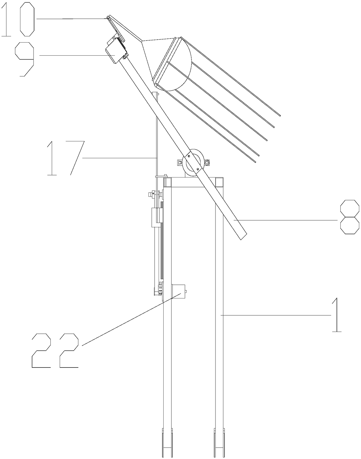
[0038] like image 3 , Figure 4 , Figure 5 and Image 6 As shown, this embodiment is a multi-angle projecting method of the rotary projecting device described in Embodiment 1, comprising the following steps:

[0039] a. After the rotary projecting device is powered on, the extension plate moves downward until the extension plate triggers the positioning switch to initialize the laser sensor, and then the synchronous belt structure drives the extension plate to move up and down until the height of the laser sensor reaches the set height ;

[0040] b. The drive motor drives the conductive slip ring to rotate, thereby driving the rotating rod to rotate;

[0041] c. When the laser sensor detects the laser light reflected from the rotating rod, control the steering gear to release the air claws to release the object, and the object ejection is completed so far.

[0042] By setting the laser sensor at different heights and controlling the rotating rod to project objects at di...


PUM


Abstract

The invention discloses a rotating throwing device and a multi-angle throwing method. The rotating throwing device comprises a frame, a drive motor, a conductive slip ring, a rotating rod, a steeringengine, a gas claw, an installation plate, a synchronous belt structure, a stretching-out plate, and a laser sensor. The drive motor is fixed on the frame, and an output end of the drive motor is provided with the conductive slip ring. The conductive slip ring is connected with a rotating rod, and the drive motor drives the conductive slip ring to rotate. The conductive slip ring drives the rotating rod to rotate. One end of the rotating rod is provided with a steering engine, and the steering engine is connected with the gas claw. The installation plate is fixed on a side surface of the frame, and the synchronous belt structure is disposed on the installation plate. One end of the stretching-out plate is connected with the synchronous belt structure, and the synchronous belt structure drives the stretching-out plate to move up and down, wherein the other end of the stretching-out plate is connected with the laser sensor. According to the multi-angle throwing method for the device, thelaser sensor is disposed at different heights, and the rotating rod is controlled to throw articles at different heights, thereby achieving the multi-angle throwing.

Description

technical field [0001] The invention relates to the field of object projection, in particular to a rotary projection device and a multi-angle projection method. Background technique [0002] Throwing sports are very common in daily life. For example, when a tennis player is training, it is necessary to throw a tennis ball to practice the player's ability to catch the ball. To realize the full automation of tennis player training, the robot is required to be able to throw tennis balls at different angles and speeds, so as to train athletes in all directions. Such a type of robot needs a multi-angle projecting device, and the research on the multi-angle projecting device is still relatively lacking on the market. Contents of the invention [0003] The purpose of the present invention is to overcome the deficiencies of the prior art, to provide a rotary projecting device, the steering gear is used to control the air claws to grab and release objects, and the conductive slip ...

Claims


Application Information

Patent Timeline
IPC IPC(8): A63B69/40A63B69/38
CPCA63B69/38A63B69/40A63B2225/093
Inventor 张东王浩楠董健陈智杰余兆昊陈之楷
Owner SOUTH CHINA UNIV OF TECH
Why Eureka
Try Eureka