Purifying device and purifying method

A purification device and fluidized bed technology, applied in chemical instruments and methods, separation methods, gas treatment, etc., can solve the problem of high energy consumption, and achieve the effect of reducing energy consumption and improving uniformity

Pending Publication Date: 2019-01-04
ZHEJIANG UNIV
View PDF8 Cites 4 Cited by
  • Summary
  • Abstract
  • Description
  • Claims
  • Application Information

AI Technical Summary

Problems solved by technology

[0008] Since the prior art needs to use the vibration generating device to maintain the biomass conductive carbon in

Method used


Image

  • Purifying device and purifying method
  • Purifying device and purifying method
  • Purifying device and purifying method

Examples


Embodiment approach 1

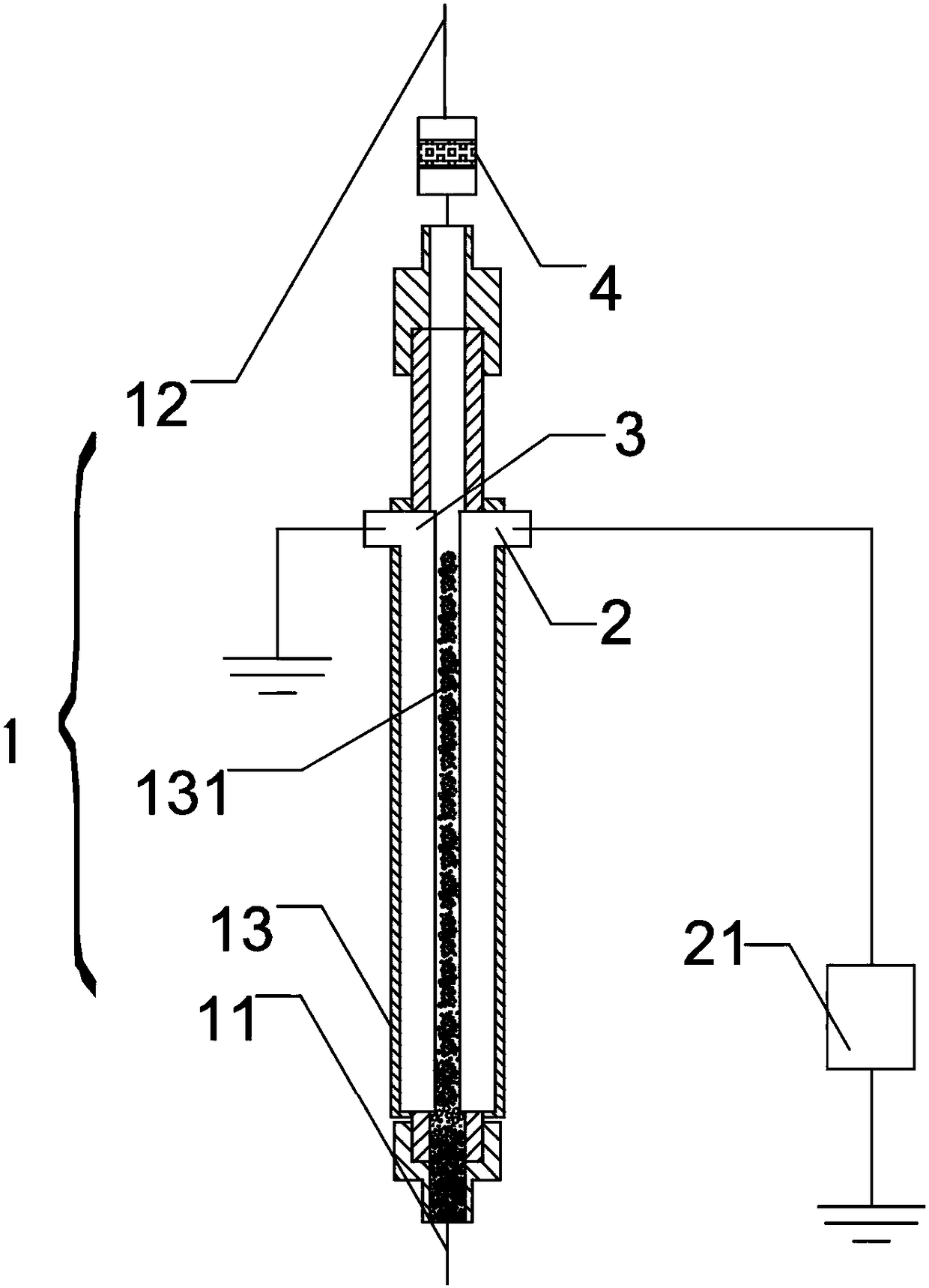
[0054] The first embodiment of the present invention provides a purification device, see figure 1 shown, including:

[0055] Fluidized bed 1, fluidized bed 1 comprises hollow reaction tube 13 and the gas inlet 11 that is arranged on reaction tube 13 two ends, gas outlet 12, is provided with biomass conductive carbon particle 131 in reaction tube 13, biomass conductive carbon particle 131 Can be in a fluidized state under the action of air flow;

[0056] The purification device also includes a high-voltage electrode 2 and a low-voltage electrode 3 respectively arranged on both sides of the fluidized bed 1;

[0057] The organic pollutant gas enters the reaction tube 13, and a potential difference is formed between the high-voltage electrode 2 and the low-voltage electrode 3, which breaks down the biomass conductive carbon particles 131 in a fluidized state and forms a discharge to degrade the organic pollutant gas.

[0058] Wherein, the reaction tube 13 can be a circular insul...

Embodiment approach 2

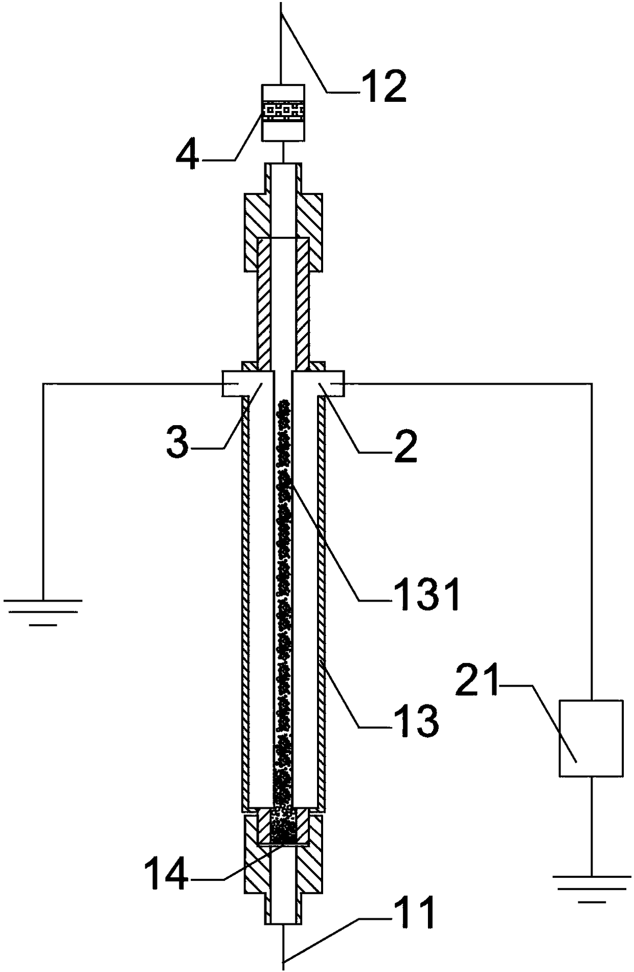
[0064] A second embodiment of the present invention provides a purification device. The second embodiment is a further improvement of the first embodiment, the main improvement is that, in the second embodiment of the present invention, see figure 2 As shown, the fluidized bed 1 also includes a gas flow distribution plate 14 arranged at one end of the reaction tube 13 close to the gas inlet 11, and a plurality of through holes are distributed on the gas flow distribution plate 14, and the aperture of the through holes is smaller than that of the biomass conductive carbon particles 131. particle size.

[0065] In this embodiment, the airflow distribution plate 14 can be made of insulating and corrosion-resistant materials, such as polytetrafluoroethylene, ceramics, etc., so that the insulating and corrosion-resistant materials can prolong the service life of the airflow distribution plate 14 as much as possible. The through holes provided in the gas flow distribution plate 14...

Embodiment approach 3

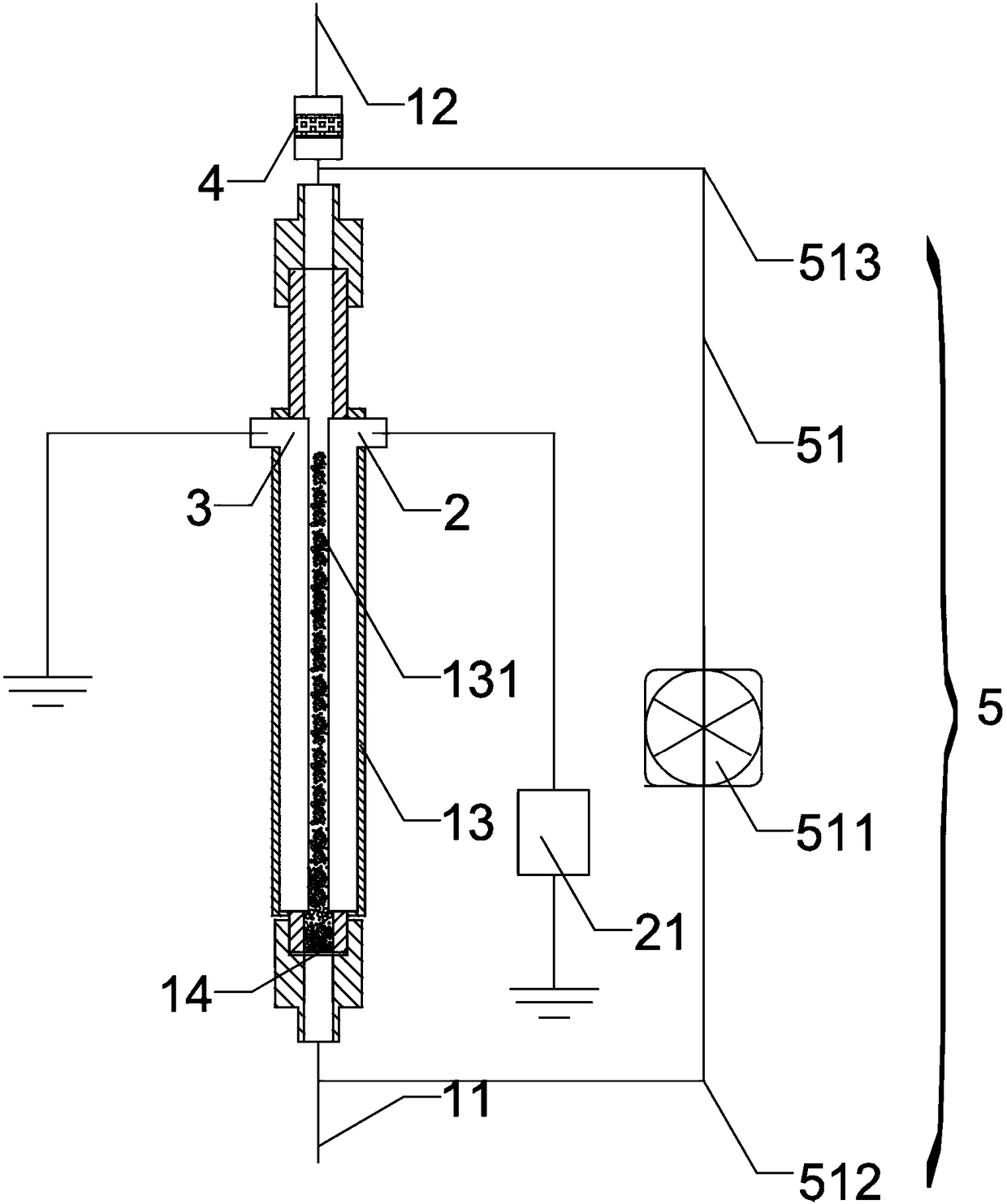
[0067] A third embodiment of the present invention provides a purification device. The third embodiment is a further improvement of the first embodiment, the main improvement is that, in the third embodiment of the present invention, see image 3 As shown, the purification unit also includes:

[0068] The circulation mechanism 5, the circulation mechanism 5 includes a circulation channel 51 connected to the gas inlet 11 and the gas outlet 12 at both ends and a circulation fan 511 arranged on the circulation channel 51, and the circulation channel 51 is provided with a circulation inlet 512 and a circulation outlet 513 ;

[0069] The background gas circulates in the circulation channel 51 and the reaction tube 13 driven by the circulation fan 511, and the biomass conductive carbon particles 131 are in a fluidized state under the action of the background gas;

[0070] The organic pollutant gas enters the circulation channel 51 through the circulation inlet 512 , circulates in ...


PUM


Abstract

The invention relates to the field of environment protection, and discloses a purifying device which comprises a fluidized bed. The fluidized bed comprises a hollow reaction pipe, a gas inlet and a gas outlet, wherein the gas inlet and the gas outlet are formed in the two ends of the reaction pipe. Biomass conductive carbon particles are arranged in the reaction pipe and can be in a fluidized state under the effect of gas flow. The purifying device further comprises a high-voltage electrode and a low-voltage electrode which are arranged on the two sides of the fluidized bed. Organic pollutantgas enters the reaction pipe, the potential difference is formed between the high-voltage electrode and the low-voltage electrode, the biomass conductive carbon particles in the fluidized state are broken down to form discharging, and the organic pollutant gas is degraded. By means of the purifying device, energy consumption can be reduced, and the organic pollutant gas degradation capacity can beimproved.

Description

technical field [0001] The invention relates to the field of environmental protection, in particular to a purification device. Background technique [0002] Organic pollutant gases (toluene, formaldehyde, etc.) are common pollutants in production and life, which not only affect human health and destroy the ecological environment, but also may cause fine particles (such as PM2.5), ozone (O 3 ) and other characteristics of regional atmospheric complex pollution problems. At present, the methods for treating organic pollutant gases mainly include absorption method (such as activated carbon), combustion method, catalytic degradation method, and decomposition method (such as photolysis, ozone decomposition, plasma decomposition) and so on. [0003] All living organic substances that can grow are collectively called biomass, which includes plants, animals and microorganisms. Biomass is a kind of solar energy. The annual carbon fixed by plant photosynthesis on the earth is as high...

Claims


Application Information

Patent Timeline
IPC IPC(8): B01D53/32B01D53/12
CPCB01D53/12B01D53/32B01D2257/708B01D2259/818B01D2253/20Y02A50/20
Inventor 肖刚庞华许伟平骆仲泱倪明江高翔岑可法
Owner ZHEJIANG UNIV
Why Eureka
Try Eureka