Machine for cutting tubes

A hose and machine technology, applied in the field of cutting devices, can solve problems such as the decrease in reliability of hydraulic pipelines

Active Publication Date: 2019-01-04
UNIFLEX HYDRAULIC
View PDF6 Cites 0 Cited by
  • Summary
  • Abstract
  • Description
  • Claims
  • Application Information

AI Technical Summary

Problems solved by technology

Because such deviations from the ideal cut can lead to a reduction in the reliability of the associated hydraulic lines, the failure of which, however, has serious consequences in individual cases

Method used


Image

  • Machine for cutting tubes
  • Machine for cutting tubes
  • Machine for cutting tubes

Examples


Embodiment Construction

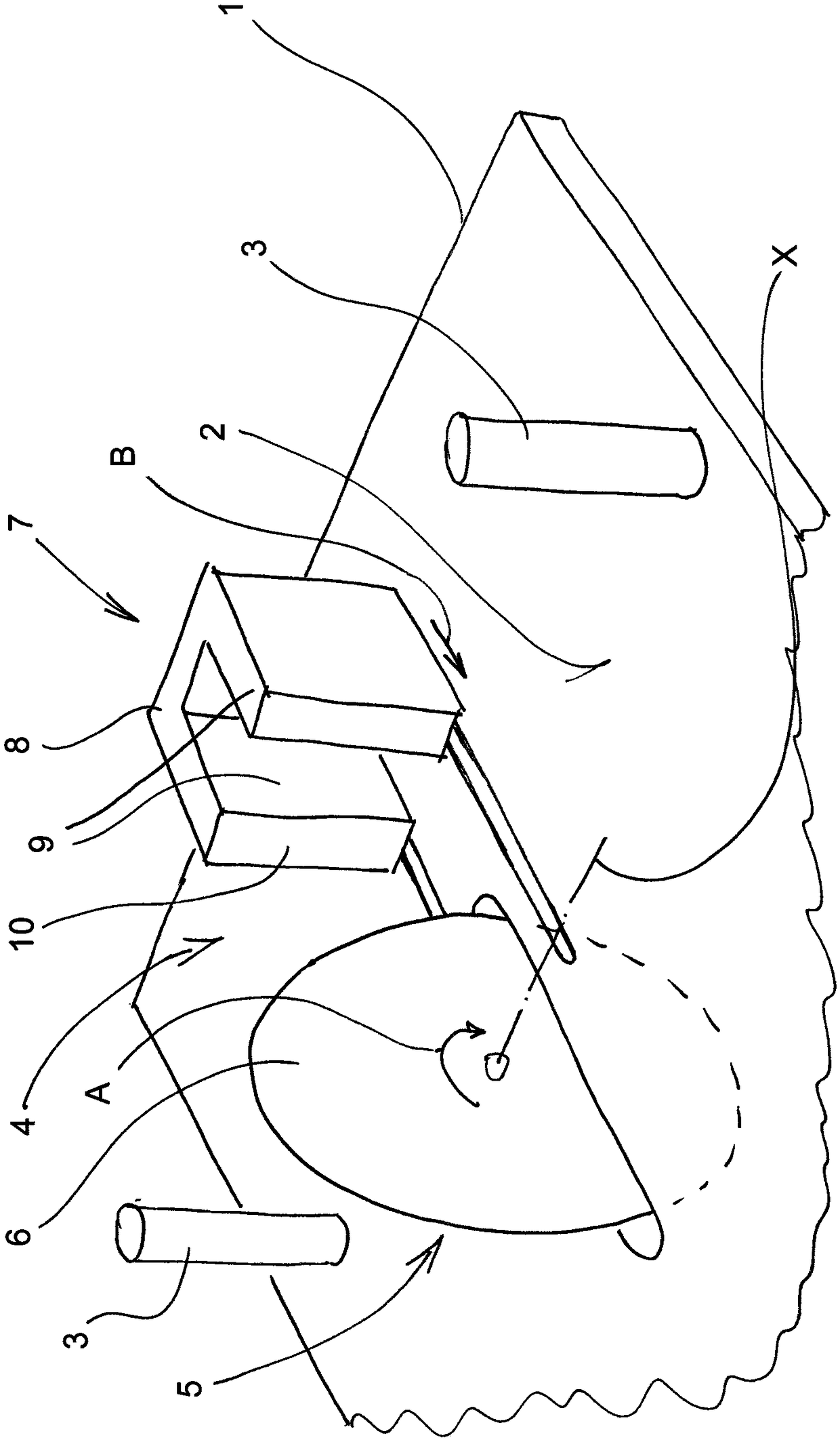
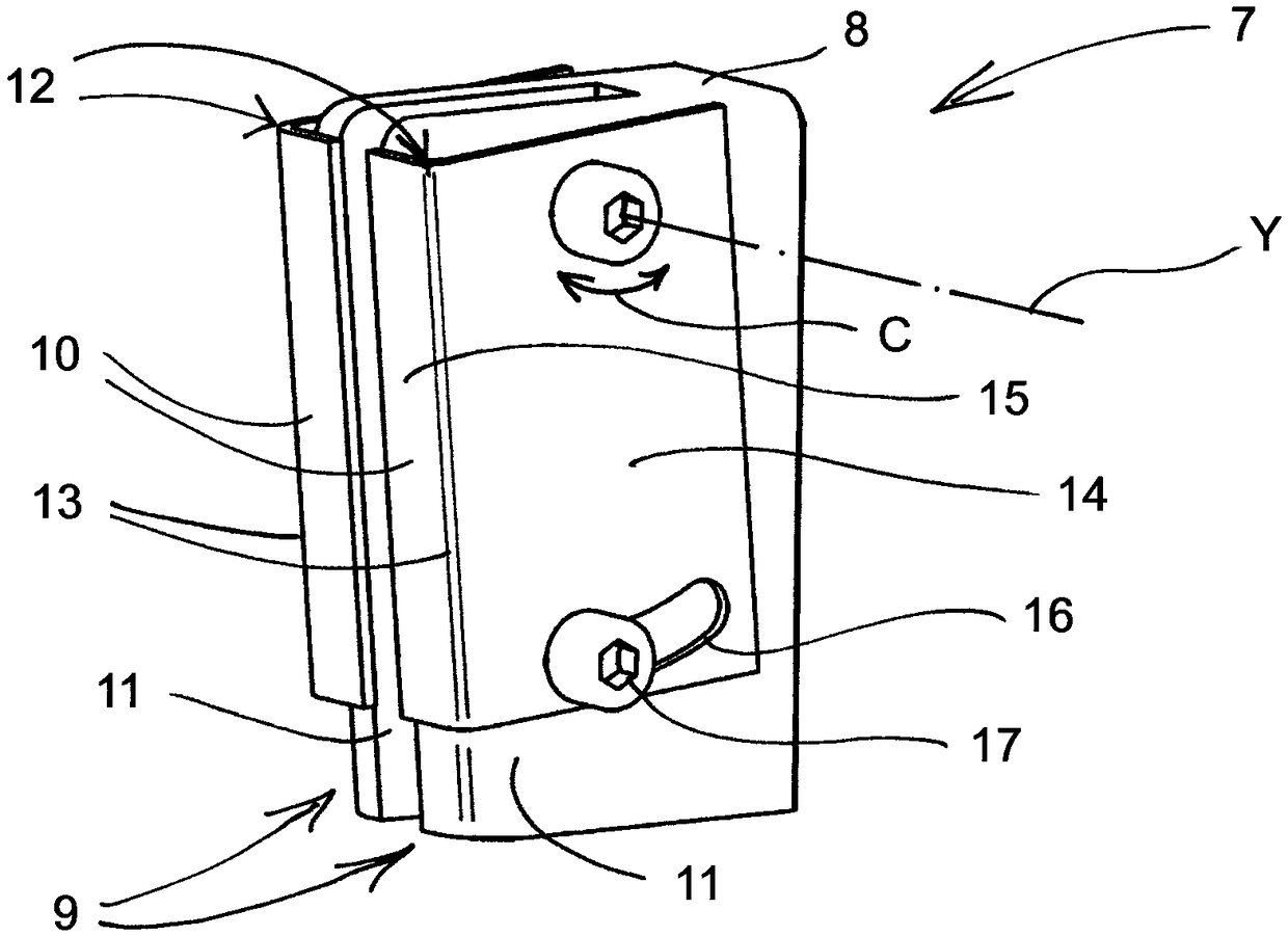
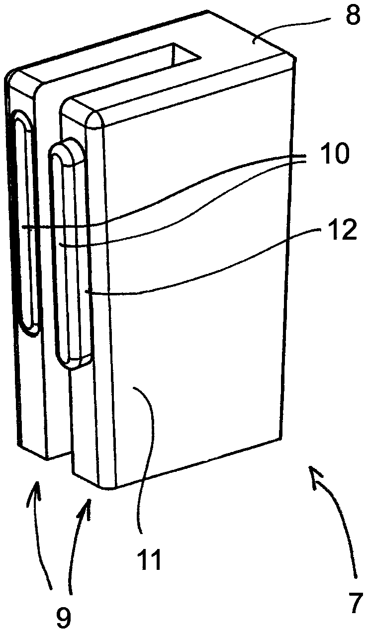
[0019] As known in the prior art (cf. for example GB 1505113) and therefore need not be specifically set forth, figure 1 The machine for cutting hoses shown schematically in includes a placement table 1 with a substantially planar hose placement surface 2, two spaced apart hose devices 3 protruding from the placement table and arranged on the hose Cutting device between equipment4. The latter comprises a sectioning tool 5 in the form of a sectioning segment 6 which is driven in rotation (arrow A) about an axis X substantially parallel to the hose placement surface 2 and which defines the A substantially vertical cutting plane. Furthermore, the sectioning device 4 includes a hose feed 7 which is movable (arrow B) parallel to the sectioning plane and parallel to the hose placement surface 2 by means of a feed mechanism (not shown) arranged below the placement table 1 . As a one-piece, substantially U-shaped feed seat 8 in horizontal section, the hose feed has two pressure part...


PUM


Abstract

The invention relates to a machine for cutting tubes, comprising a support table, at least two tube rests protruding from said table and arranged at a distance from one another, and a separating device arranged between same. The support table has a substantially flat tube-supporting surface, and the separating device has a cutting knife and a tube feed (7) which can move parallel to the separatingplane and has two thrust pieces (9) arranged on both sides of the separating plane, each having a tube contact surface (10). In addition, at least one first of the thrust pieces (9) has a thrust piece attachment (12) adjustably attached to a carrier (11) and having the associated tube contact surfaces (10). In an alternative embodiment of the invention, a tube feed that can moved in parallel to the separating plane can comprise a feed block, on which two thrust pieces (9') are formed, arranged on both sides of the separating plane and each having a tube contact surface (10'), wherein the feedblock (8') is adjustably mounted in such a way that the position of the two tube contact surfaces (10') can be changed relative to the separating plane.

Description

technical field [0001] The invention relates to a machine for cutting hoses, comprising a stand, at least two spaced-apart hose devices protruding from the stand, and a cutting device arranged between the two hose devices, Wherein, the placement table has a substantially planar hose placement surface, and the sectioning device has a sectioning knife, which extends in a sectioning plane arranged substantially perpendicular to the hose placement surface, and the The slicing device also has a hose feed movable parallel to the slicing plane with two pressure elements arranged on both sides of the slicing plane and each having a hose contact surface. Background technique [0002] A machine of the above-mentioned type, a so-called "hose splitter", is known (for example from document GB 1505113) and is used in practice. The machine is used in particular for cutting off hose sections from a hose stock, for example for cutting a hose section from a hose stock prior to further proces...

Claims


Application Information

Patent Timeline
IPC IPC(8): B26D3/16B26D7/01
CPCB26D3/16B26D7/0608B26D2007/013Y10T83/0596Y10T83/323Y10T83/343Y10T83/8752
Inventor C.鲍姆加特纳E.威库姆
Owner UNIFLEX HYDRAULIC
Why Eureka
Try Eureka