Embedded part bonding fixture

A bonding and fixture technology, which is applied in the direction of workpiece clamping devices, connecting components, manufacturing tools, etc., can solve the problems of contact with the back of the glass panel, etc., and achieve convenient operation, high bonding efficiency and precision, and bonding. The effect of fewer processes

Active Publication Date: 2019-01-22
NINGBO FOTILE KITCHEN WARE CO LTD
View PDF7 Cites 0 Cited by
  • Summary
  • Abstract
  • Description
  • Claims
  • Application Information

AI Technical Summary

Problems solved by technology

[0005] The above-mentioned bonding tool is only suitable for the decorative panel that is only in contact with the front of the glass panel, that is, the shape of the decorative panel is also thin and flat. For the decorative strip with a U-shaped cross section, the aforementioned bonding tool is not suitable for use. Since the glass panel is to be embedded in the groove of the decorative strip, not only the end surface of the decorative strip will contact the front of the glass panel, but it will also contact the back of the glass panel

Method used


Image

  • Embedded part bonding fixture
  • Embedded part bonding fixture
  • Embedded part bonding fixture

Examples


Embodiment Construction

[0032] The present invention will be further described in detail below in conjunction with the accompanying drawings and embodiments.

[0033] Such as Figure 1-13 Shown is a preferred embodiment of the present invention.

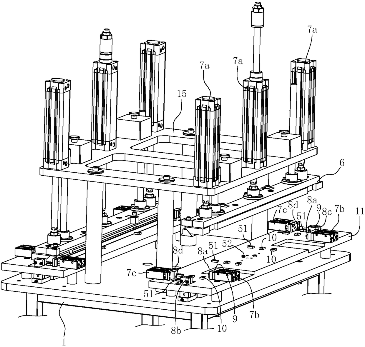
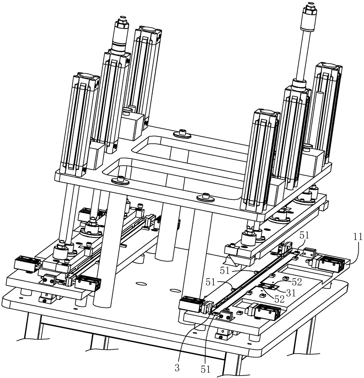
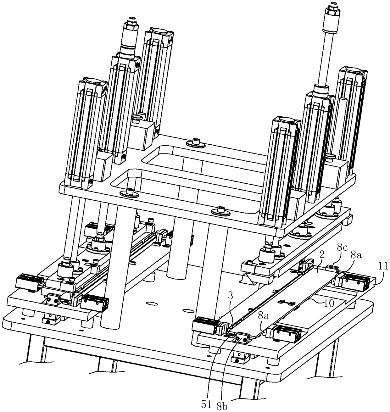
[0034] A bonding fixture for embedded parts, including a frame 1, the frame 1 has a table 11 for a glass panel 2 and a decorative strip 3 to rest on, and the cross section of the decorative strip 3 is U-shaped, so that a groove part 31 is formed, such as Figure 13 As shown, at least one side of the table top 1 is provided with an adhesive structure; in this embodiment, two sets of adhesive structures are respectively provided on the front and back sides of the table top 11 .

[0035] Adhesive structure includes

[0036] The decorative strip positioning structure is set on the table 11 to constrain and limit the decorative strip 3; the decorative strip positioning structure includes a plurality of decorative strips fixed on the table 11 to position the le...


PUM


Abstract

The invention relates to an embedded part bonding fixture, which comprises a table board; a bonding structure, wherein the bonding structure comprises a decorative strip positioning structure; a pressing plate assembly arranged above the table board; a vertical driving structure used for driving the pressing plate assembly to move up and down perpendicular to the table board; a front positioning block used for positioning the front edge of a glass panel; a left positioning block and a right positioning block, which are respectively used for positioning the left edge and rear edge of the glasspanel; a rear positioning block used for positioning the rear edge of the glass panel; a front pushing block arranged on the table board and is driven by a front driving structure to slide back and forth, wherein the front pushing block is used for pushing the glass panel backwards and embedding the rear part of the glass panel into a clamping groove part of the decorative strip. The device can automatically embed the glass panel into the clamping groove part of the decorative strip with a U-shaped cross section, and can perform well pressure maintaining on the glass panel in the clamping groove part so as to ensure the automation of the process of bonding the decorative strip with the U-shaped cross section to the glass panel.

Description

technical field [0001] The invention relates to a bonding tool for bonding a certain part to another part, in particular to a bonding fixture for an embedded part bonding a decorative strip to a glass panel. Background technique [0002] In order to make the overall appearance of the range hood more beautiful and generous, glass panels with decorative panels (or decorative strips) are installed on the surface of some high-end range hood shell parts. The decorative panels are made of stainless steel. Due to the special material of the glass panel The decorative panel needs to be fixed on the glass panel by bonding, and the decorative panel is generally only bonded to the front of the glass panel. [0003] At present, there are mainly two ways to bond the decorative panel to the back of the glass panel: one is the traditional bonding, which uses manual bonding of the decorative panel to the glass panel one by one. Under the premise of increased pressure, the processing cost w...

Claims


Application Information

Patent Timeline
IPC IPC(8): B25B11/00F16B11/00
CPCB25B11/00F16B11/006
Inventor 叶群茅忠群诸永定李立波
Owner NINGBO FOTILE KITCHEN WARE CO LTD
Why Eureka
Try Eureka