Compression Refrigerator

A refrigerator and compression technology, which is applied in the direction of refrigerators, compressors, refrigeration components, etc., can solve problems such as difficulty in approaching targets, increased product costs, and difficulty in refrigerant flow control.

Active Publication Date: 2021-07-20
EBARA REFRIGERATION EQUIP & SYST CO LTD
View PDF11 Cites 0 Cited by
  • Summary
  • Abstract
  • Description
  • Claims
  • Application Information

AI Technical Summary

Problems solved by technology

[0008] (1) If the difference between LTD at high load and low load is small and strict control is required, a high-precision (high-priced) temperature sensor or pressure sensor is required, resulting in an increase in product cost
[0009] (2) When the cooling load or cooling water temperature fluctuates greatly and the frequency of fluctuation is high, it may be difficult to control the flow rate of the refrigerant due to the delay in the actual opening and closing of the control valve.
[0010] (3) In practical application, when the heat transfer tube is polluted, it is difficult to approach the target LTD

Method used


Image

  • Compression Refrigerator
  • Compression Refrigerator
  • Compression Refrigerator

Examples


Embodiment Construction

[0042] Below, refer to Figure 1 to Figure 10 Embodiments of the compression refrigerator of the present invention will be described. exist Figure 1 to Figure 10 In , the same reference numerals are attached to the same or corresponding constituent elements, and overlapping descriptions are omitted.

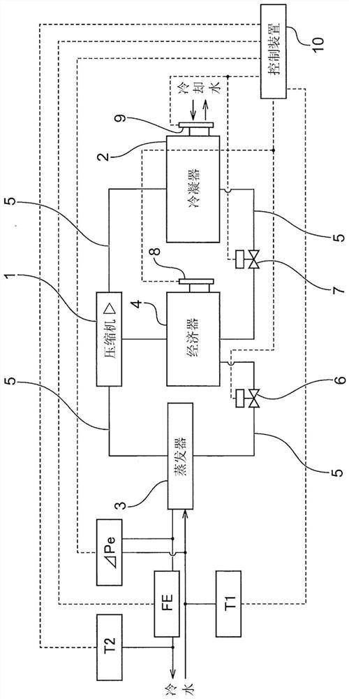
[0043] figure 1 It is a schematic diagram showing one embodiment of the compression refrigerating machine of the present invention. Such as figure 1 As shown, the compression refrigerator includes: a compressor 1, which compresses the refrigerant; a condenser 2, which uses cooling water (cooling fluid) to cool the compressed refrigerant gas to condense it; an evaporator 3, It takes heat from the cold water (cooled fluid) to exert the cooling effect of evaporating the refrigerant; as an intercooler, the economizer 4 is arranged between the condenser 2 and the evaporator 3, and the refrigerant piping for the refrigerant circulation 5. The above-mentioned devices are connected...


PUM


Abstract

The compression refrigerating machine provided by the present invention does not need high-precision and expensive measuring instruments such as temperature sensors and pressure sensors, and can use general-purpose cheap and simple measuring instruments, and can ensure the best cooling capacity according to the refrigeration load or operating point in the evaporator. Refrigerant inventory. The compression refrigerating machine includes: a first flow control unit installed in the pipe connecting the evaporator and the economizer; a second flow control unit installed in the pipe connecting the economizer and the condenser; A flow control unit and / or the opening and closing control of the second flow control unit; a refrigeration load rate calculation unit, which calculates the refrigeration load rate during the operation of the compression refrigerator. The control device compares the calculated value of the cooling load rate calculated by the cooling load rate calculation unit with the preset value of the cooling load rate, and controls the evaporation by the first flow control unit and / or the second flow control unit based on the comparison result Refrigerant holding capacity of the device.

Description

technical field [0001] The present invention relates to a compression refrigerator equipped with an evaporator, a compressor, and a condenser, and in particular to a compression refrigerator equipped with a flooded evaporator. The flooded evaporator is equipped with a heat transfer tube group inside the housing. Pass cold water into the heat transfer tube and fill the shell with liquid refrigerant. Background technique [0002] Conventionally, compression refrigerators used in refrigerating and air-conditioning equipment and the like are composed of refrigerant piping connecting an evaporator, a compressor, a condenser, and an expansion valve (expansion mechanism), and the evaporator is constituted by a closed system in which refrigerant is sealed. The refrigerant absorbs heat from the cold water (cooled fluid) and evaporates to exert the cooling effect. The compressor compresses the refrigerant gas evaporated in the evaporator to become a high-pressure refrigerant gas. The ...

Claims


Application Information

Patent Timeline
Patent Type & Authority Patents(China)
IPC IPC(8): F25B1/053F25B41/00F25B41/20F25B43/00F25B49/02F25B41/40
CPCF25B1/053F25B41/00F25B43/006F25B49/02F25B2700/21172F25B2700/21173F25B2400/13F25B2600/2515F25B41/20
Inventor 金哲石山健山田宏幸
Owner EBARA REFRIGERATION EQUIP & SYST CO LTD
Why Eureka
Try Eureka