
Process for producing a molded part

A technology for forming parts and forming molds, which is applied in the field of manufacturing forming parts and can solve problems such as the limitation of the maximum increase of the size of the cavity

Active Publication Date: 2019-01-29
ENGEL AUSTRIA
View PDF4 Cites 1 Cited by
  • Summary
  • Abstract
  • Description
  • Claims
  • Application Information

AI Technical Summary

Problems solved by technology

[0002] In the case of similar methods, the problem arises that molded parts should be produced that require a larger amount of melt than can be supplied at one time by the injection unit of the molding machine
However, the size of molded parts that can be produced in this way is of course limited due to the maximum expandability of the cavity, because closing forces must be transmitted between the mold parts in order to prevent the melt from flowing out of the cavity

Method used


Image

  • Process for producing a molded part
  • Process for producing a molded part
  • Process for producing a molded part

Examples


Embodiment Construction

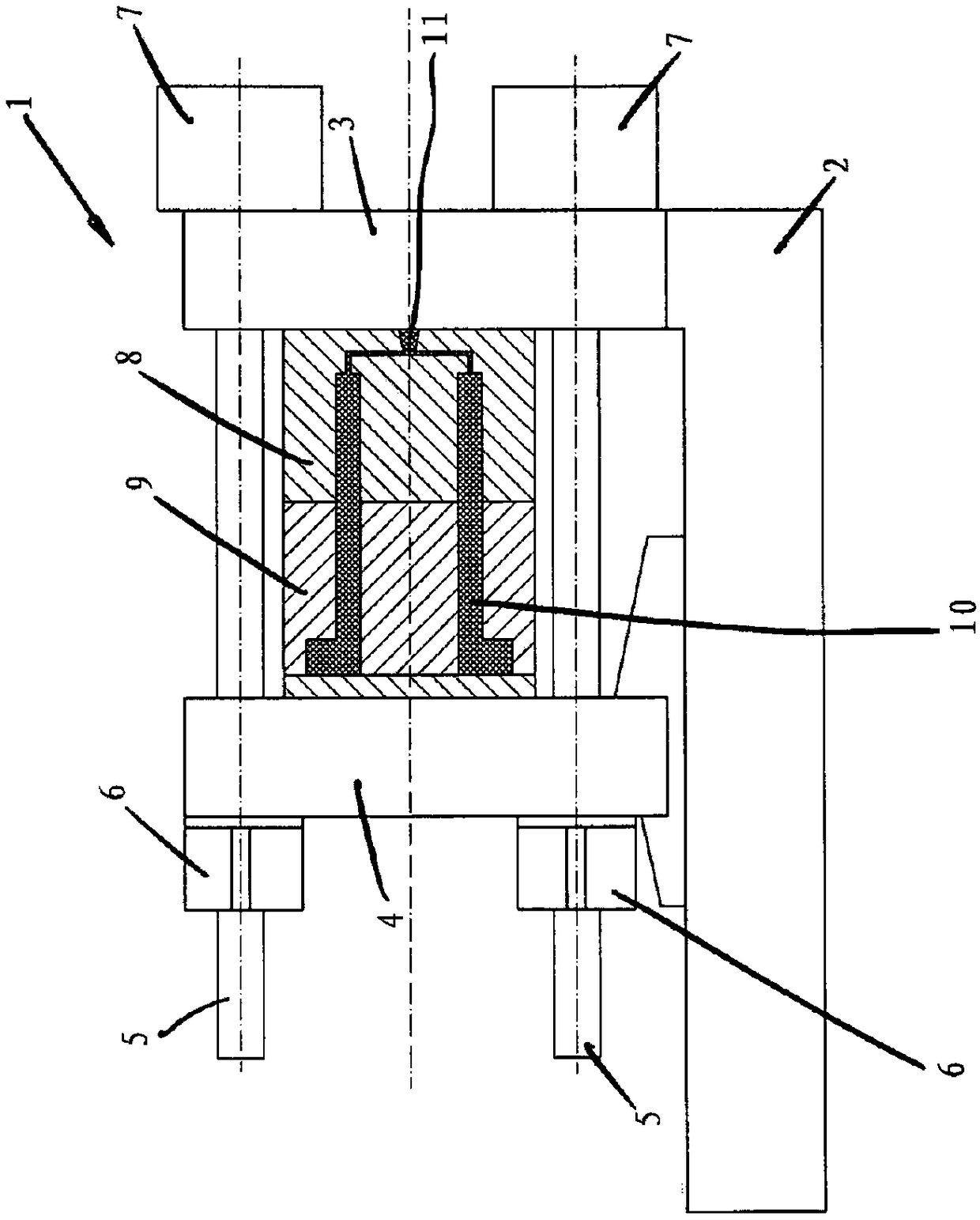
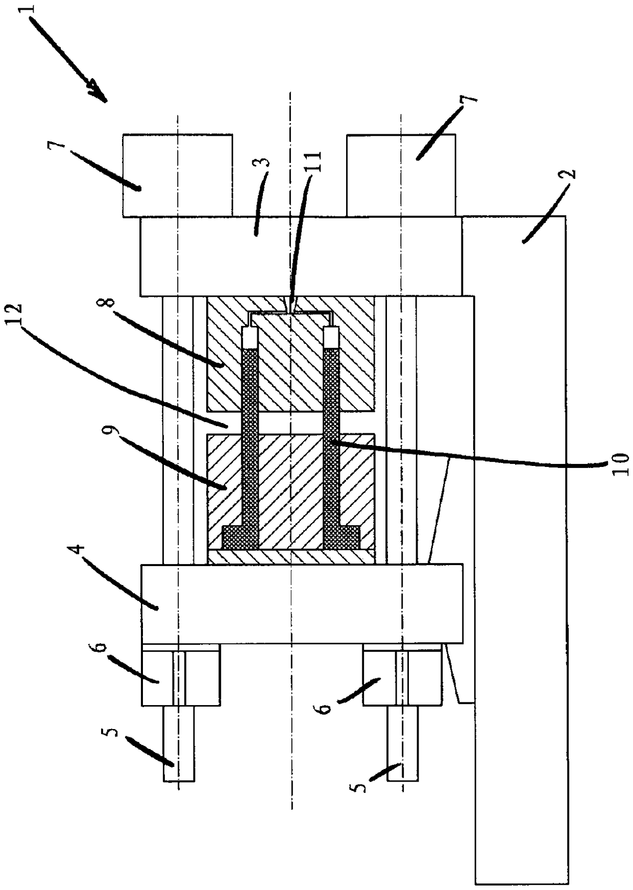
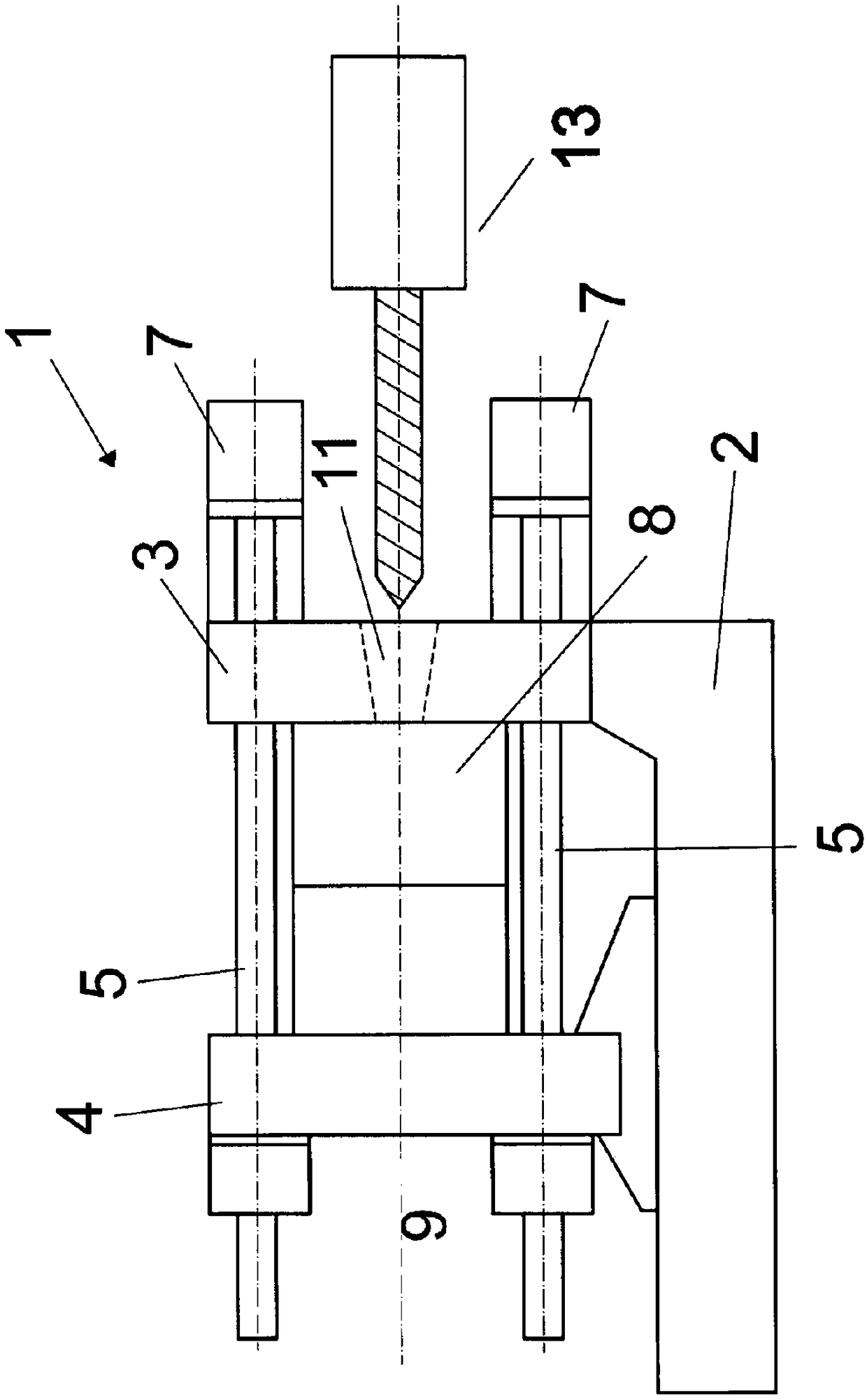
[0020] figure 1 Shown is a closed unit 1 of a molding machine (here a two-platen injection molding machine) with a machine base 2, a first mold clamping plate 3 fixedly connected to the machine base 2 and movable on the machine base 2 The second mold clamping plate 4. In this exemplary embodiment, the cavity arranged around the longitudinal axis of the machine is formed between a first mold part 8 clamped on the first mold clamping plate 3 and a second mold part 9 clamped on the second mold clamping plate 4 between.

[0021] The displacement of the second tool clamping plate 4 can be carried out by means of a rapid stroke mechanism (not shown (because it corresponds to the prior art)). The closing force counteracting the expansion force exerted by the melt on the cavity can be applied to the tension beam 5 via the pressure pad 7 and to the second locking device 6 (known per se as a separate locking nut here). On the second mold clamping plate 4.

[0022] exist figure 1 In...


PUM


Abstract

A method of manufacturing a molded part includes inserting melt into a cavity of a first tool part, and the first tool part and a second tool part are moved away from one another during or after the insertion of the melt by moving a mold clamping plate relative to a mold clamping plate such that in the first tool part or in a second tool part an at least partial clearance of a first or second zoneof the cavity takes place, and a gap is formed between the first tool part and the second tool part. Melt is further inserted into the cleared area of the cavity, and the gap is bridged by an at least already partially solidified section of the melt. A holding force is transmitted from the second tool part through the partially solidified section of the melt bridging the gap to the first tool part.

Description

technical field [0001] The invention relates to a method for producing molded parts having the features of the preamble of claim 1 . Background technique [0002] In similar methods, the problem arises that molded parts are to be produced which require a larger amount of melt than can be supplied at one time by the injection unit of the molding machine. In order to solve the above-mentioned problems, it is known to introduce the required amount of melt continuously in partial quantities into the cavity, which can be enlarged for this purpose. Individual partial quantities of the melt can in turn be supplied by a single injection unit or by a plurality of injection units. Scrubbing tools are also known for this purpose. However, the size of molded parts which can be produced in this way is of course limited due to the maximum expandability of the cavity, since closing forces must be transmitted between the mold parts in order to prevent the melt from escaping from the cavit...

Claims


Application Information

Patent Timeline
Patent Type & Authority Applications(China)
IPC IPC(8): B29C45/64
CPCB29C45/56B29C2045/5695B29C2045/569B29C2045/563B29C45/641B29C45/67B29C45/26
Inventor H·蔡德尔霍费尔G·克拉默
Owner ENGEL AUSTRIA
Features
  • Generate Ideas
  • Intellectual Property
  • Life Sciences
  • Materials
  • Tech Scout
  • Unparalleled Data Quality
  • Higher Quality Content
  • 60% Fewer Hallucinations
Learn More